Font Suspension Assembly
9/30/2010 to 10/12/2010

 First
step is to put the shock mount flanges back on the upper
arms. The bolts were good enough to reuse but I bought
new lock washers
First
step is to put the shock mount flanges back on the upper
arms. The bolts were good enough to reuse but I bought
new lock washers |

 Finally
got the steering knuckles and spindles back from the machine
shop. They did a nice job but they managed to destroy
the other spacer. I could have done that myself...
I cleaned and degreased all the bearings to get the
preservative goop out.
Finally
got the steering knuckles and spindles back from the machine
shop. They did a nice job but they managed to destroy
the other spacer. I could have done that myself...
I cleaned and degreased all the bearings to get the
preservative goop out. |
 Now
I can fit the kingpins to the control arms. Here I
have the new pin and rubber rings installed and I am
installing the metal wedge that keeps the pin from turning
inside the kingpin.
Now
I can fit the kingpins to the control arms. Here I
have the new pin and rubber rings installed and I am
installing the metal wedge that keeps the pin from turning
inside the kingpin. |

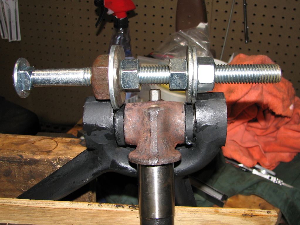 This
bad picture from the manual shows the special tool
Studebaker used to keep the arm from flexing as the pin is
tightened. I don't have this tool so this is my
homebrew version make from a 5/8" bolt and some nuts and
washers. I wonder if it will work...
This
bad picture from the manual shows the special tool
Studebaker used to keep the arm from flexing as the pin is
tightened. I don't have this tool so this is my
homebrew version make from a 5/8" bolt and some nuts and
washers. I wonder if it will work... |

 The
manual says to use the tool to spread the arm .010" then
install the end caps. I could not get it to open up
that much but it did move. I think the goal here is to
keep the caps from flexing the arm when they are tightened.
This could cause the pin to bind.
The
manual says to use the tool to spread the arm .010" then
install the end caps. I could not get it to open up
that much but it did move. I think the goal here is to
keep the caps from flexing the arm when they are tightened.
This could cause the pin to bind.Next it is big wrench time. I was not sure now this was supposed to work so I centered the pin by eye then tightened the caps a little at a time switching sides |
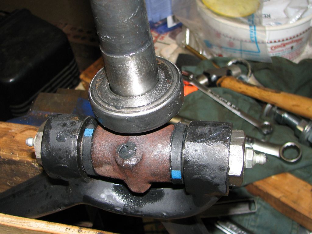 Looks
like a winner. The pin is tight with no wiggle but
moves freely. I packed the upper thrust bearing with
grease and installed the bearing and shims. I also
tightened the grease fittings in the caps.
Looks
like a winner. The pin is tight with no wiggle but
moves freely. I packed the upper thrust bearing with
grease and installed the bearing and shims. I also
tightened the grease fittings in the caps. |
 This
cork gaskets goes in the yoke that holds the kingpin in the
spindle. The cork gasket is old stock and cracked when
I installed it. Still it should work OK. The
yoke has a keyway for a
woodruff key on the end of the kingpin.
This
cork gaskets goes in the yoke that holds the kingpin in the
spindle. The cork gasket is old stock and cracked when
I installed it. Still it should work OK. The
yoke has a keyway for a
woodruff key on the end of the kingpin. |
 After
greasing the needle bearing and bushing the spindle slides
right on. Here the yoke is in place but the washer and
nut are not yet installed.
After
greasing the needle bearing and bushing the spindle slides
right on. Here the yoke is in place but the washer and
nut are not yet installed. |
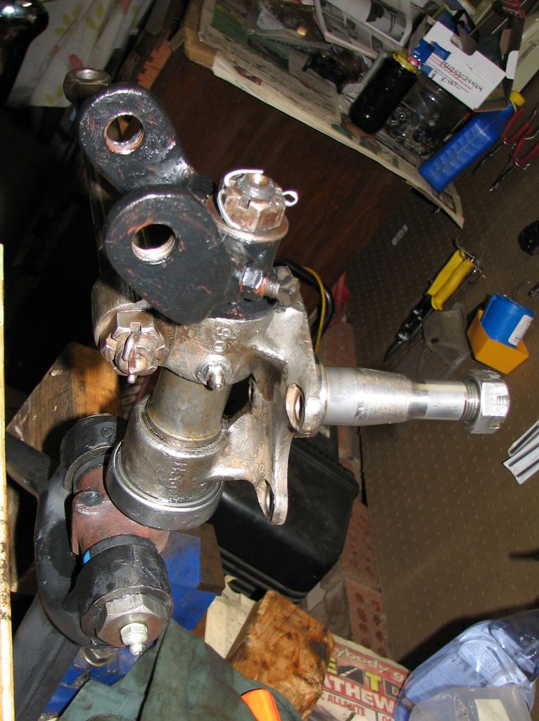 The
finished product. The yoke is in place, nut tightened, and
a new cotter pin installed. I also installed the grease
fitting in the spindle. Now I get to repeat on the other
side and the arms are ready to go back in the car.
The
finished product. The yoke is in place, nut tightened, and
a new cotter pin installed. I also installed the grease
fitting in the spindle. Now I get to repeat on the other
side and the arms are ready to go back in the car. |
 The
other (drivers) side. This one went back together pretty
much the same except I used too many shims on the kingpin and
had to take it apart again to fix it. I carefully measured
for the shims but ended up removing all of them. I am not
sure what happened but it feels great so I am leaving it be.
The
other (drivers) side. This one went back together pretty
much the same except I used too many shims on the kingpin and
had to take it apart again to fix it. I carefully measured
for the shims but ended up removing all of them. I am not
sure what happened but it feels great so I am leaving it be. |
 Here
are all the parts to install the control arm in the driver's
side. From left to right we have the front mount and its
bolts, the new front bushings, the bushing hardware, the shims,
the control arm and spindle, and rear bushings and hardware.
Here
are all the parts to install the control arm in the driver's
side. From left to right we have the front mount and its
bolts, the new front bushings, the bushing hardware, the shims,
the control arm and spindle, and rear bushings and hardware. |
 It
is easier to work on this stuff out of the car so I installed
the front mount and bushings on the floor. The bolt is
only loosely installed because I don't want to clamp the
bushings in place until I have the arm positioned properly.
I also slipped the inner rear bushing on.
It
is easier to work on this stuff out of the car so I installed
the front mount and bushings on the floor. The bolt is
only loosely installed because I don't want to clamp the
bushings in place until I have the arm positioned properly.
I also slipped the inner rear bushing on. |
 Tap
the bolts though, slip the rear of the arm in the rear mount,
and install the front mount very loosely. Everything is
going smoothly so far.
Tap
the bolts though, slip the rear of the arm in the rear mount,
and install the front mount very loosely. Everything is
going smoothly so far. |

 The
last (rear) bushing slipped right in so I reinstalled the shims
under the front mount and cranked the front mount bolts tight.
You can see the shims clearly in the right picture.
The
last (rear) bushing slipped right in so I reinstalled the shims
under the front mount and cranked the front mount bolts tight.
You can see the shims clearly in the right picture. |
 Bushing
and frame bolts are tight and everything looks good. Time
to install a shock.
Bushing
and frame bolts are tight and everything looks good. Time
to install a shock. |

 Bolting
the shock in place is easy enough. one of the bolts was
pretty corroded so I replaced it with a new grade 5 nut and
bolt. Now for the tricky part. The shock arm to
frame hardware is in the picture on the right. I have new
isolation bushings and a new upper washer too.
Bolting
the shock in place is easy enough. one of the bolts was
pretty corroded so I replaced it with a new grade 5 nut and
bolt. Now for the tricky part. The shock arm to
frame hardware is in the picture on the right. I have new
isolation bushings and a new upper washer too. |

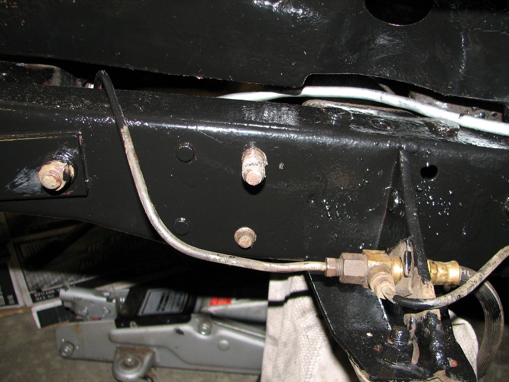
 Now
things are getting interesting. At left you can see the
hole in the wheel well required to snake this very long bolt
through the bushings, shock arm, and frame rail. But this
bolt is not long enough. The end of the bolt does not
reach the bottom of the frame. Now
things are getting interesting. At left you can see the
hole in the wheel well required to snake this very long bolt
through the bushings, shock arm, and frame rail. But this
bolt is not long enough. The end of the bolt does not
reach the bottom of the frame.
|
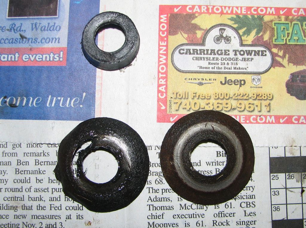
 Here
is the last surviving old bushing. The idea is the dished
washers and bolt squish the cylindrical bushings into this UFO
shape. But I am not sure how to get the bolt shoved though
enough to get the nut on. Maybe someone pushing from above
can compress it enough. I will try it tomorrow. Time
for bed. Here
is the last surviving old bushing. The idea is the dished
washers and bolt squish the cylindrical bushings into this UFO
shape. But I am not sure how to get the bolt shoved though
enough to get the nut on. Maybe someone pushing from above
can compress it enough. I will try it tomorrow. Time
for bed. |
 OK,
a new day and a new attempt. Let's see how things are
supposed to work. I put the old shock on the bench and
used a shorter bolt to pull things together. Looks like I
am trying to do the right thing here.
OK,
a new day and a new attempt. Let's see how things are
supposed to work. I put the old shock on the bench and
used a shorter bolt to pull things together. Looks like I
am trying to do the right thing here.
|
 My
first thought was to put a bar clamp or big channel locks on the
bolt and squeeze it down. But I could not find an
angle that would work. Then I found that I could put the
bar clamp on the arm of the shock. So I took out the upper
bushing to get some working room, pulled the lower bushing flat,
and used the bar clamp to hold it in the squished position. My
first thought was to put a bar clamp or big channel locks on the
bolt and squeeze it down. But I could not find an
angle that would work. Then I found that I could put the
bar clamp on the arm of the shock. So I took out the upper
bushing to get some working room, pulled the lower bushing flat,
and used the bar clamp to hold it in the squished position.
|
 I
then put the top bushing back in. I still could not get
the nut on so I had my daughter push on the top of the
bolt with a long metal rod. That did it! I cranked
that sucker down. It looks great. In an attempt to
make this easier on the other side I put those bushings in my
test rig and left them squished. Maybe it will help. I
then put the top bushing back in. I still could not get
the nut on so I had my daughter push on the top of the
bolt with a long metal rod. That did it! I cranked
that sucker down. It looks great. In an attempt to
make this easier on the other side I put those bushings in my
test rig and left them squished. Maybe it will help. |
 I
installed the control arm and spindle on the passenger side.
That went the same as the driver's side except I still have not
found a shock absorber so that fun step is deferred for now.
I then went to install the lower pin though the spring.
The manual is very clear that the spring should be centered in
the yoke before putting the pin in. On the driver's side
it lined up perfectly. However on the passenger side I
could not even get the yoke over the spring. After some
head scratching I figured out that the only way to make this
work is to move the spring. I
installed the control arm and spindle on the passenger side.
That went the same as the driver's side except I still have not
found a shock absorber so that fun step is deferred for now.
I then went to install the lower pin though the spring.
The manual is very clear that the spring should be centered in
the yoke before putting the pin in. On the driver's side
it lined up perfectly. However on the passenger side I
could not even get the yoke over the spring. After some
head scratching I figured out that the only way to make this
work is to move the spring.
|
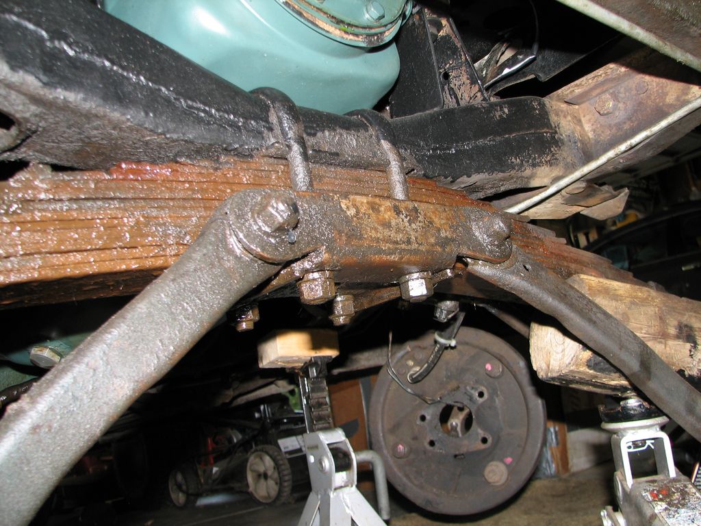
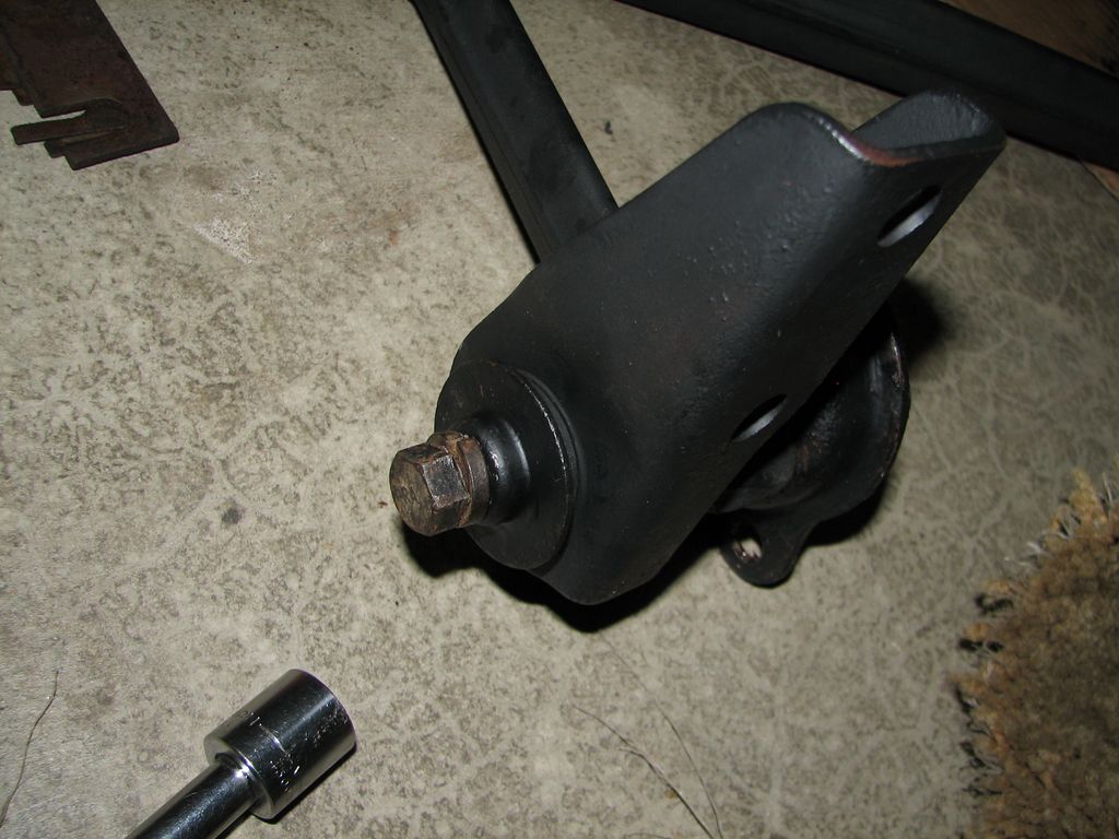
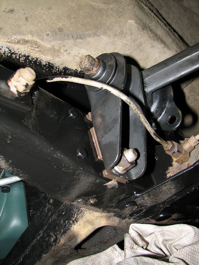
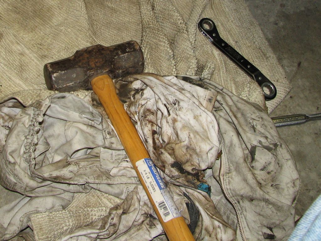 The
spring is held to the frame by these U-bolts. I loosened
them up then took a ball-peen hammer and a block of wood to the
end of the spring to try and shift it. It moved a tiny,
tiny bit. The problem with hitting a spring is that it is
a spring. It is designed to absorb energy and
return to shape. So I got out the REAL hammer. That
worked! As you can see above the yoke is almost perfectly
centered.
The
spring is held to the frame by these U-bolts. I loosened
them up then took a ball-peen hammer and a block of wood to the
end of the spring to try and shift it. It moved a tiny,
tiny bit. The problem with hitting a spring is that it is
a spring. It is designed to absorb energy and
return to shape. So I got out the REAL hammer. That
worked! As you can see above the yoke is almost perfectly
centered. |

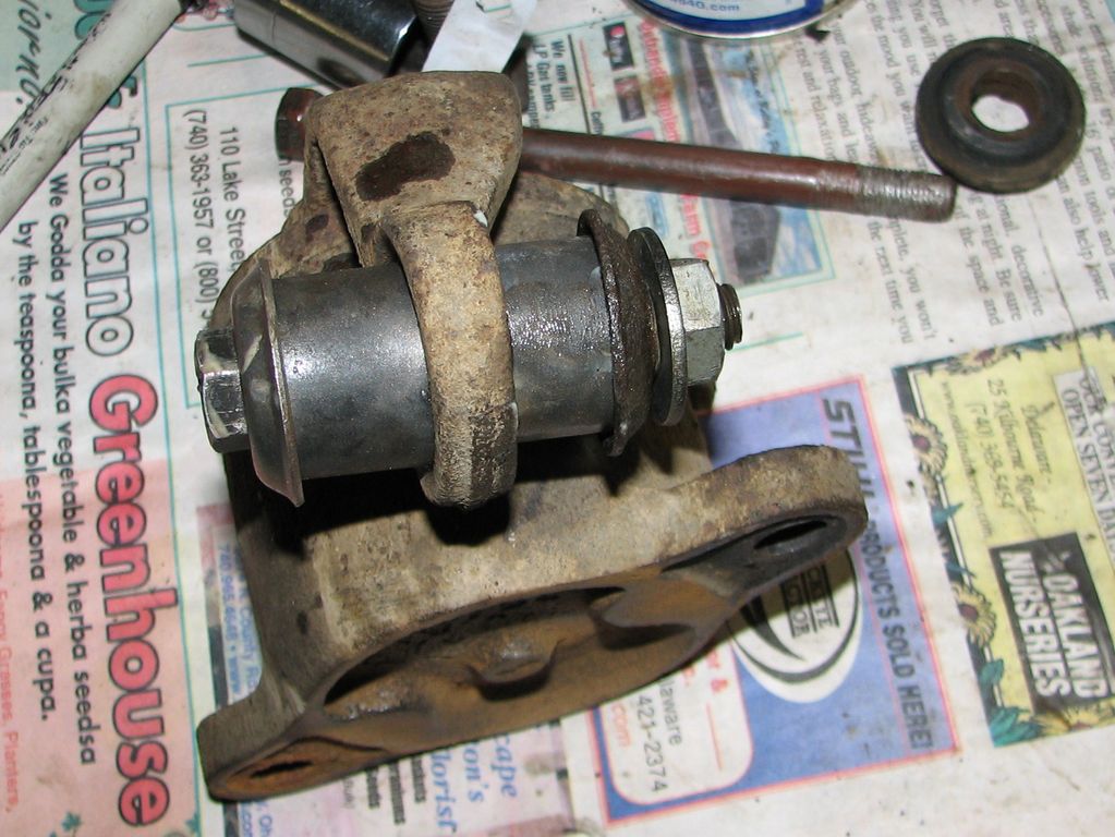
 The
pin has this locking plate. When I took it apart I could
not figure out what good it did but I was very careful to
replace it just the way it was when I removed it. I
must be really dense because it was not until I had the pin
installed that I realized how this was supposed to work.
So I took the pin back out, flipped the plate, and reinstalled.
Some nimrod before me had installed the plates wrong. This
looks much better. But now I have another problem... The
pin has this locking plate. When I took it apart I could
not figure out what good it did but I was very careful to
replace it just the way it was when I removed it. I
must be really dense because it was not until I had the pin
installed that I realized how this was supposed to work.
So I took the pin back out, flipped the plate, and reinstalled.
Some nimrod before me had installed the plates wrong. This
looks much better. But now I have another problem... |
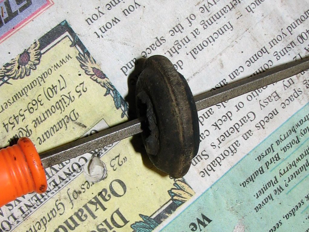
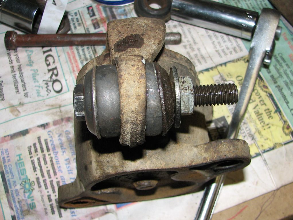
 The
#*$&@& pin has play in it! When I took all this apart I
cleaned and inspected the pins but totally failed to notice how
badly worn they are. I am not doing all this work to leave
slop in the suspension so now this job is on hold until I can
get new pins. Looks like a couple of vendors have them
(whew!). I am hoping I can get away with just replacing
the pin. If I have to get new bushings in the spring that
will be a whole new world of suck. I am taking that gamble
because when I put the pin in just a little it seems tight.
If the bushings are cheap enough I might pick them up just in
case. The
#*$&@& pin has play in it! When I took all this apart I
cleaned and inspected the pins but totally failed to notice how
badly worn they are. I am not doing all this work to leave
slop in the suspension so now this job is on hold until I can
get new pins. Looks like a couple of vendors have them
(whew!). I am hoping I can get away with just replacing
the pin. If I have to get new bushings in the spring that
will be a whole new world of suck. I am taking that gamble
because when I put the pin in just a little it seems tight.
If the bushings are cheap enough I might pick them up just in
case. |
 The
new pins and bushings arrived so we can get back to work.
As I suspected the old bushings are pretty good. I ran the
new pins in the old bushings and compared the play to the new
bushing. There is certainly more play in the old bushing
but not enough to make it worth messing with. The bushings
were about $8 each so I will just keep them. The
new pins and bushings arrived so we can get back to work.
As I suspected the old bushings are pretty good. I ran the
new pins in the old bushings and compared the play to the new
bushing. There is certainly more play in the old bushing
but not enough to make it worth messing with. The bushings
were about $8 each so I will just keep them. |

 Again
the manual makes it very clear that the yoke is supposed to be
centered in over the spring and yet when I put the new pin in I
was not paying attention and did this. Stupid. I
took the pin out, whacked the spring a couple times, and tried
again. Much better the second time.
Again
the manual makes it very clear that the yoke is supposed to be
centered in over the spring and yet when I put the new pin in I
was not paying attention and did this. Stupid. I
took the pin out, whacked the spring a couple times, and tried
again. Much better the second time. |
 And
the other side...
And
the other side... |
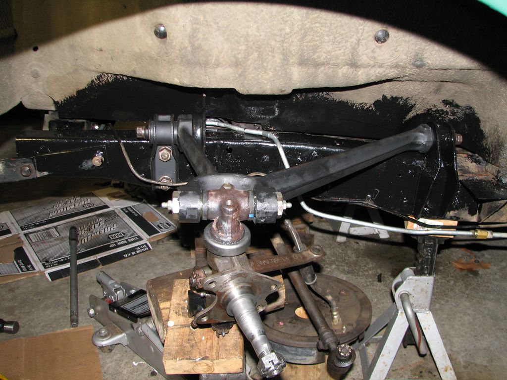
 Now
the control links can go in. It took a little tweaking to
get everything lined up but it looks great. I also
re-tightened the spring u-bolts Now
the control links can go in. It took a little tweaking to
get everything lined up but it looks great. I also
re-tightened the spring u-bolts |

 Next
I can hook up the tie rod ends. The driver's side outer
tie rod end had a badly worn cover. This is where not
throwing anything way comes in handy. Here is my
collection of old tie rod ends. The middle one has a torn
up cover but the top and bottom ones look good. On the
right we have the lucky winner. Next
I can hook up the tie rod ends. The driver's side outer
tie rod end had a badly worn cover. This is where not
throwing anything way comes in handy. Here is my
collection of old tie rod ends. The middle one has a torn
up cover but the top and bottom ones look good. On the
right we have the lucky winner. |
 There!
That looks good. This is the drivers side. The other
side is going to wait until the shock is installed. There!
That looks good. This is the drivers side. The other
side is going to wait until the shock is installed. |
 Before
reinstalling the brakes I greased everything up. The zerk
on the front side leaked a little. I did not have it tight
enough.
Before
reinstalling the brakes I greased everything up. The zerk
on the front side leaked a little. I did not have it tight
enough.
|
 The
finished product
I also finally found a passenger side shock absorber. I
cleaned and painted it. The new shock will get installed
as soon as the paint dries. but until then
The
finished product
I also finally found a passenger side shock absorber. I
cleaned and painted it. The new shock will get installed
as soon as the paint dries. but until then
|
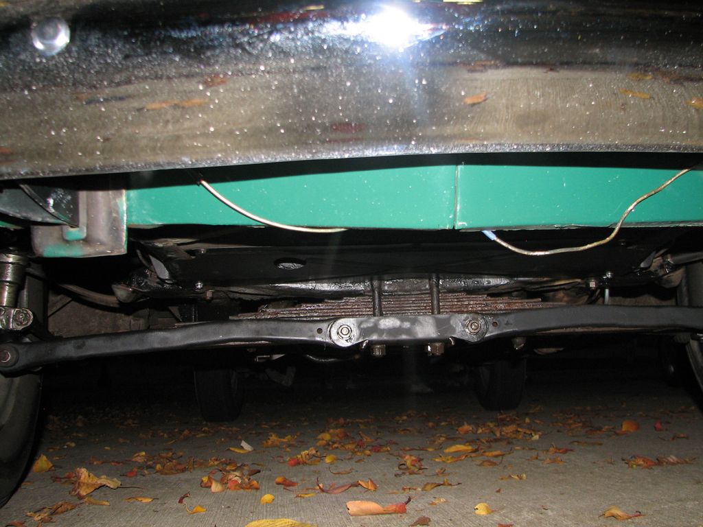
 Yet
another shot of the brakes. We are a brake drum and tire
away from putting this down on the ground. The other side
went together pretty much the same. The shock mount was
just as much of a pain
Yet
another shot of the brakes. We are a brake drum and tire
away from putting this down on the ground. The other side
went together pretty much the same. The shock mount was
just as much of a pain |
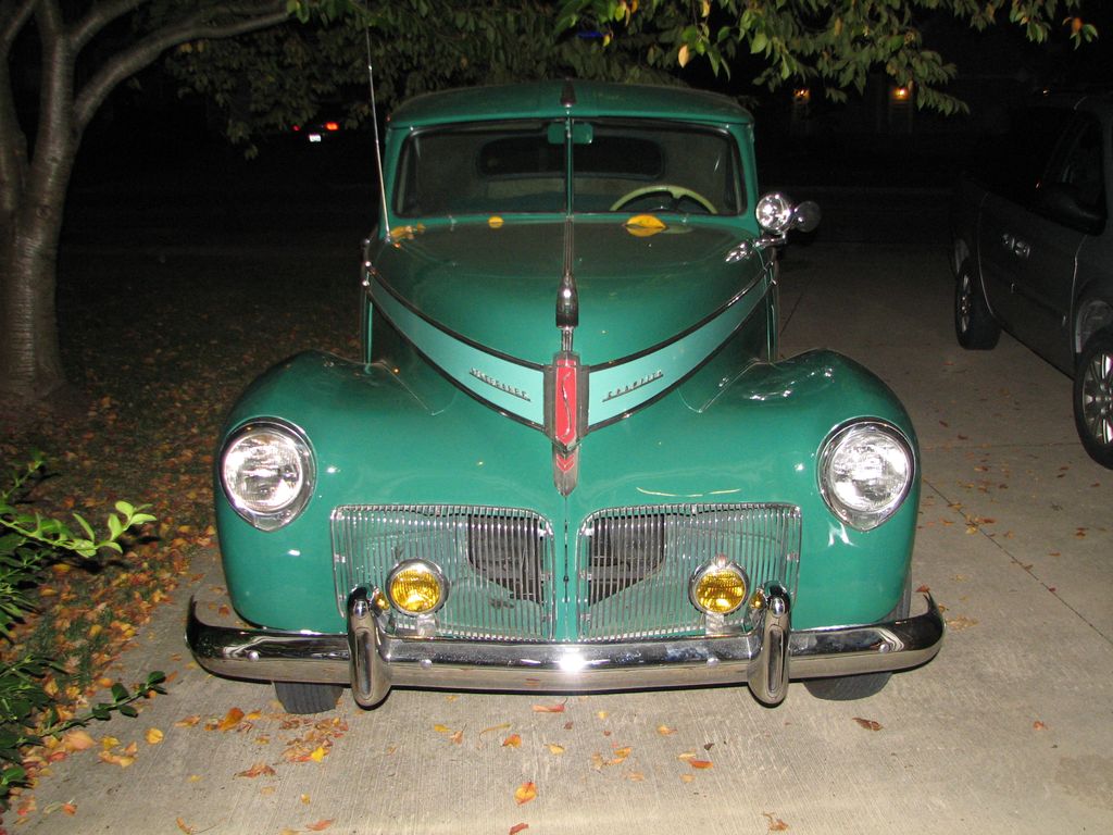 It
is a car again. The garage floor was TRASHED but I
forgot to take a picture. Hopefully I can get an alignment
this week and the car is done. It
is a car again. The garage floor was TRASHED but I
forgot to take a picture. Hopefully I can get an alignment
this week and the car is done. |