Front Suspension Teardown
9/18/2010 to 9/20/2010
 The car's handling has gotten a bit more squirrelly than
usual. Not that it was ever great. I have
replaced all the worn tie rod ends but it is time to fix up
everything else. My initial plan was to rebuild the
kingpins and replace all the bushings in the control arms.
Plans change though... The car's handling has gotten a bit more squirrelly than
usual. Not that it was ever great. I have
replaced all the worn tie rod ends but it is time to fix up
everything else. My initial plan was to rebuild the
kingpins and replace all the bushings in the control arms.
Plans change though...The exploded view at right is from the parts book. Click on it for a larger version. The image is distorted at the top because the book would NOT lay flat on the scanner. When I mention a part below I will reference the diagram index numbers. Since the pictures are from the passenger side of the car I will be using the numbers from the left side of the exploded view. |

 First step is to get the brakes out of the way. After
pulling the drum and hub the backing plate comes off with
the four bolts around the spindle. A coat hanger
serves well to hang the brakes out of the way so they don't
hang on the brake hose.
First step is to get the brakes out of the way. After
pulling the drum and hub the backing plate comes off with
the four bolts around the spindle. A coat hanger
serves well to hang the brakes out of the way so they don't
hang on the brake hose. Now we can see the upper control arm (1204-7), king pin (1203-1), spindle (1202-1), tie rod (connects to 1202-33), and spring (figure that one out!). |
 Second
step is to disconnect the steering tie rod. Sometimes
a sharp whack with a hammer will break the tie rod end loose
but I don't like beating on things. Especially
expensive threaded tie rod ends when I have this tool that
makes it easy. This is designed for modern ball joints
but works fine here if I use a wrench for a spacer.
Second
step is to disconnect the steering tie rod. Sometimes
a sharp whack with a hammer will break the tie rod end loose
but I don't like beating on things. Especially
expensive threaded tie rod ends when I have this tool that
makes it easy. This is designed for modern ball joints
but works fine here if I use a wrench for a spacer. |

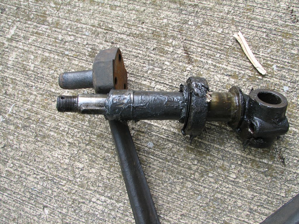
 A
threaded pin goes through the eye of the spring. The
eye is also threaded. This connects the spring to the
spindle yoke (1203-10). A bolt in the end of the pin
goes holds the lower control arm (1511-1) in place.
Once the bolt is removed and the arm pulled off (the wrench
on the right) the pin unscrews from the spring using the
left wrench.
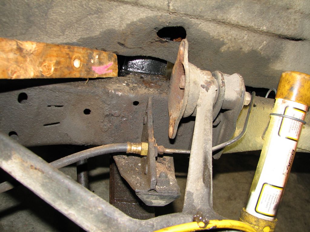
A
threaded pin goes through the eye of the spring. The
eye is also threaded. This connects the spring to the
spindle yoke (1203-10). A bolt in the end of the pin
goes holds the lower control arm (1511-1) in place.
Once the bolt is removed and the arm pulled off (the wrench
on the right) the pin unscrews from the spring using the
left wrench.The image on the right shows the pin, bolt and related hardware. |
 Next
the shock comes out. The body of the shock bolts onto
the control arm via the flange you can see on the right.
The lever arm of the shock bolts to the frame via a long
bolt that goes all the way though the arm, two bushings, and
the frame rail. The hole in the wheel well is so you
can get that bolt out.
Next
the shock comes out. The body of the shock bolts onto
the control arm via the flange you can see on the right.
The lever arm of the shock bolts to the frame via a long
bolt that goes all the way though the arm, two bushings, and
the frame rail. The hole in the wheel well is so you
can get that bolt out.
It was at this point I discovered that my air impact wrench was going to be the go-to tool for this project. These bolts were rusty and tight but the impact wrench knocked them off no problem. |
 Here
is the shock absorber, the long bolt, and the remains of the
bushings. The end of the bolt was beat to hell.
When I tried to move the shock I found out why. The
video at right shows the sad tale. Both front shocks
are frozen. As the suspension moves the arm was just
whacking up and down on the bolt until the bushings and bolt
were mangled. I will have to get new shocks.
That is going to be expensive.
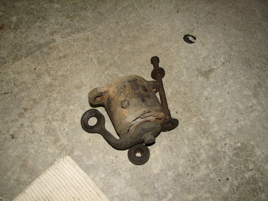
Here
is the shock absorber, the long bolt, and the remains of the
bushings. The end of the bolt was beat to hell.
When I tried to move the shock I found out why. The
video at right shows the sad tale. Both front shocks
are frozen. As the suspension moves the arm was just
whacking up and down on the bolt until the bushings and bolt
were mangled. I will have to get new shocks.
That is going to be expensive. In the meanwhile I can just leave them off. It seems I did not have shocks before anyway. |

 Now
we can remove the control arm (1204-7) from the frame.
The pins on the arm go through rubber bushings (1204-44) in
the frame mounts (1204-32 and 1204-39). The bushings
are bolted in place with big washers (1204-47). The
rear bushing bolt at right comes out first. No room
for the air wrench her so I did it the hard way.
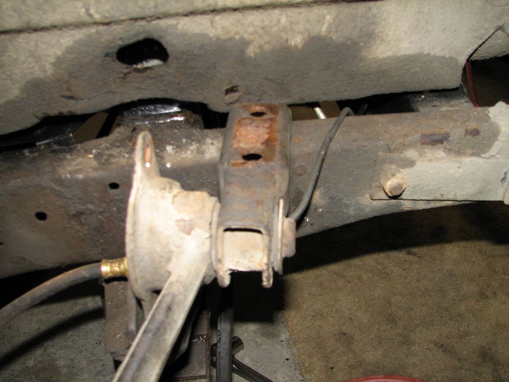
Now
we can remove the control arm (1204-7) from the frame.
The pins on the arm go through rubber bushings (1204-44) in
the frame mounts (1204-32 and 1204-39). The bushings
are bolted in place with big washers (1204-47). The
rear bushing bolt at right comes out first. No room
for the air wrench her so I did it the hard way. |
 Then
the front mount (1204-32) is unbolted from the frame.
The air wrench DOES work here! Shims (1204-38) behind
this mount adjust the camber of the front wheels.
Then
the front mount (1204-32) is unbolted from the frame.
The air wrench DOES work here! Shims (1204-38) behind
this mount adjust the camber of the front wheels.Once the front mount is off the frame the entire assembly comes out leaving a big gaping hole. I forgot to mention earlier that I lowered the spring onto a jack stand with a jack. The spring is almost unloaded but not quite. |
 Now
the control arm moves to my vice. The vice was the
second most useful tool of the day after the air impact
wrench. First front frame mount (1204-32), washer
(1204-47), and bushings (1204-44) come off the control arm.
Now
the control arm moves to my vice. The vice was the
second most useful tool of the day after the air impact
wrench. First front frame mount (1204-32), washer
(1204-47), and bushings (1204-44) come off the control arm. |
 Next
the shock mount can come off the arm. This is not
really required but there is some rust here and I want to
get everything cleaned and painted. Again the air
wrench makes this work easy.
Next
the shock mount can come off the arm. This is not
really required but there is some rust here and I want to
get everything cleaned and painted. Again the air
wrench makes this work easy. |

 Now
it time to take the rest of this mess apart. There is
a tapered pin that keeps the upper pin (1204-9) from
rotating in the king pin (1203-1). This just taps out
with a brass rod. Never turn down a brass rod if you
can get one.
Now
it time to take the rest of this mess apart. There is
a tapered pin that keeps the upper pin (1204-9) from
rotating in the king pin (1203-1). This just taps out
with a brass rod. Never turn down a brass rod if you
can get one.With the pin out the end caps (1204-17) come off the upper pin (1204-9). This took the biggest wrench I own (1 1/8"). I have never used it before. Always buy the larger wrench set. Once the end caps are off the upper pin (1204-9) slides right out of the control arm (1204-7) and the king pin/spindle assembly falls off. |

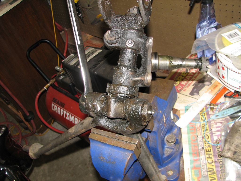
 A
big castle nut holds the lower spring yoke (1203-10) on the
bottom of the king pin (1203-1). Once that is out I
used a brass drift to tap the king pin out. The king
pin then slides right out of the spindle (1202-1). The
picture of the king pin on the right shows the thrust
bearing (1203-9) and a couple of shims (1202-22).
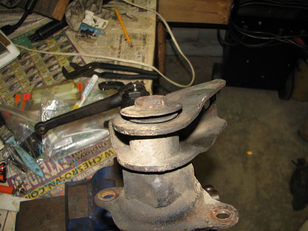
A
big castle nut holds the lower spring yoke (1203-10) on the
bottom of the king pin (1203-1). Once that is out I
used a brass drift to tap the king pin out. The king
pin then slides right out of the spindle (1202-1). The
picture of the king pin on the right shows the thrust
bearing (1203-9) and a couple of shims (1202-22). |

 Here
is where I got really brain-dead stupid. The spindle
(1202-1) contains a needle bearing on top (1202-8), a spacer
in the middle (1202-14), and a bronze bushing at the bottom
(1202-10). The manual is VERY clear. It says to
use a press from the bushing end to push all three parts out
of the spindle. I don't have a press but I do have a
hammer and I am willing to use it. I found a bushing driver
the same size as the bushing and tried to tap everything
apart. It would not move. This was the right
time to quit and take it all to the machine shop. I
did not quit.
Here
is where I got really brain-dead stupid. The spindle
(1202-1) contains a needle bearing on top (1202-8), a spacer
in the middle (1202-14), and a bronze bushing at the bottom
(1202-10). The manual is VERY clear. It says to
use a press from the bushing end to push all three parts out
of the spindle. I don't have a press but I do have a
hammer and I am willing to use it. I found a bushing driver
the same size as the bushing and tried to tap everything
apart. It would not move. This was the right
time to quit and take it all to the machine shop. I
did not quit.Instead I thought maybe I could tap from the bearing down. That worked (I thought) but the bearing end of the spacer is BIGGER than the bushing end. The space is also a very thin-walled steel tube. By the time I figured all this out the spacer was mangled. Eventually I gave up and removed it in pieces. For those of you keeping score at home I now need two shocks and a spacer tube. If I can't find one this could get ugly. At least the shocks were worn out. This is all on me and I can't put it back together until I find this part. While doing that I will spend my time working on cleaning and painting these parts. |
 Speaking
of ugly this is what all the pins on the control arm
(1204-7) look like. The pitting is pretty severe.
I am not sure if this is something to be concerned about.
I will probably just put it back together this way. If
the rough pins cause the bushings to fail twice as fast they
will still be good for 35 years...
Speaking
of ugly this is what all the pins on the control arm
(1204-7) look like. The pitting is pretty severe.
I am not sure if this is something to be concerned about.
I will probably just put it back together this way. If
the rough pins cause the bushings to fail twice as fast they
will still be good for 35 years... |
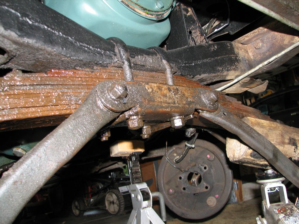
 These are the lower control arms (1511-1). These are all twisted up. I
suspect years of hitting tree branches, dead deer, and
pedestrians. The u-bolts that hold the spring to the
frame also holds the bracket that holds these control arms.
Both arms are bent up. So is the center bracket.
The bolts were a bit rusty but the trusty impact wrench took
care of them.
These are the lower control arms (1511-1). These are all twisted up. I
suspect years of hitting tree branches, dead deer, and
pedestrians. The u-bolts that hold the spring to the
frame also holds the bracket that holds these control arms.
Both arms are bent up. So is the center bracket.
The bolts were a bit rusty but the trusty impact wrench took
care of them. |