Clutch
June 5-10, 2005
So in May my Dad helped pull-start the car. It took some doing but now it runs fine. My best guess is some crap was stuck in the carb. A carb rebuild is in this car's future (as is a real fuel filter). I took the car for a spin, got gas, and then just as I was pulling the car in the garage the clutch pedal went soft and the car stalled out. I tried to start it but the clutch would not disengage. Yikes. The clutch itself was totally rebuilt around 1985 but has very few miles on it. I figured the linkage was a likely suspect.
 I
crawled under the car and the linkage was intact but the operating shaft
did not seem to rotate very much. My first thought was that the
clutch throwout bearing had slipped off the levers that operate it.
To figure it all out I decided to go ahead and pull the transmission to
see what was up. 45 minutes later the transmission is on my bench.
That was easy! The transmission fees like a new one. The bearings
are solid and smooth. I was going to take off the cover but why
mess with a good thing? I
crawled under the car and the linkage was intact but the operating shaft
did not seem to rotate very much. My first thought was that the
clutch throwout bearing had slipped off the levers that operate it.
To figure it all out I decided to go ahead and pull the transmission to
see what was up. 45 minutes later the transmission is on my bench.
That was easy! The transmission fees like a new one. The bearings
are solid and smooth. I was going to take off the cover but why
mess with a good thing? |
 To
keep you oriented here is the exploded view of the clutch linkage in my
car (a 3G in case you were wondering). I pulled everything but the
actual clutch pedal and the shaft it pivots on. To
keep you oriented here is the exploded view of the clutch linkage in my
car (a 3G in case you were wondering). I pulled everything but the
actual clutch pedal and the shaft it pivots on.
The diagram below shows the actual clutch. The end of the clutch operating shaft (0206-1 at left) is coupled to the lever shaft (0203-11 below) with the coupler (0206-26 at left). This coupler sort of acts like a universal joint to handle any movement between the engine and the frame of the car. |
|
 I
cleaned and painted the driveshaft, rear motor mount and cross-member
while I had it all out. The rust was almost non-existent but now
we should be good for another 60 years. Here is the painted shaft
leaning up next to my 1967 Simplicity lawn tractor (previously my oldest
vehicle). I
cleaned and painted the driveshaft, rear motor mount and cross-member
while I had it all out. The rust was almost non-existent but now
we should be good for another 60 years. Here is the painted shaft
leaning up next to my 1967 Simplicity lawn tractor (previously my oldest
vehicle). |
|
|
  Both
shafts and the coupler that joins them had wear in the clevis pin holes
too. A lot of slop there! Both
shafts and the coupler that joins them had wear in the clevis pin holes
too. A lot of slop there! |
|
|
|
|
|
|


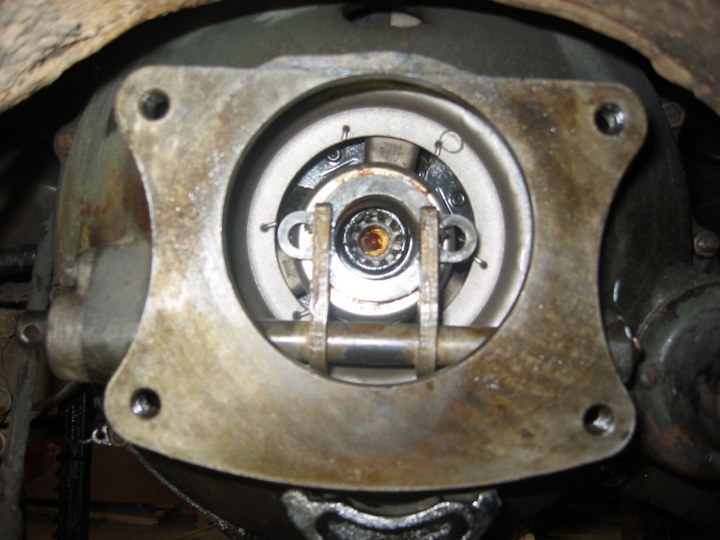 Here
is the same shot with the Lever Shaft and Throwout Bearing installed.
The bushings that the shaft pivots in feel really good. I half
expected them to be really worn. At this point I was stuck for a
couple of days waiting for the Operating Shaft. Here
is the same shot with the Lever Shaft and Throwout Bearing installed.
The bushings that the shaft pivots in feel really good. I half
expected them to be really worn. At this point I was stuck for a
couple of days waiting for the Operating Shaft. |
|
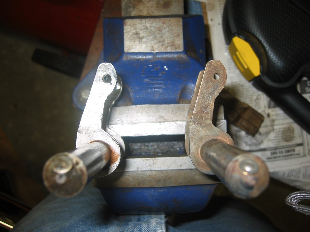
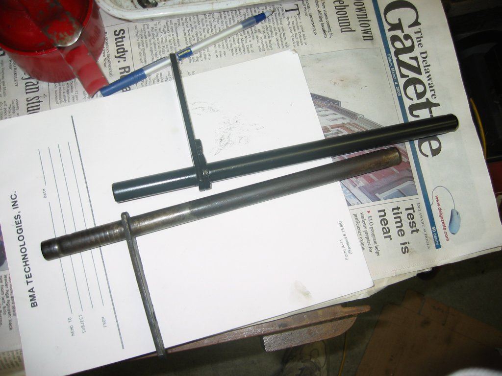 Finally
I got the new shaft. The new one is on top. It looks so nice
because I painted it. The lever on the new shaft is attached
differently than the one on the old shaft. I have heard these had a
nasty habit of rotating on the shaft and causing the clutch to fail. I
could not get mine to rotate but maybe it did in the past because the old
shaft is at a slightly different angle than the new one. Just in case
I scribed the new shaft so if the lever comes loose I will know where it
belongs. Finally
I got the new shaft. The new one is on top. It looks so nice
because I painted it. The lever on the new shaft is attached
differently than the one on the old shaft. I have heard these had a
nasty habit of rotating on the shaft and causing the clutch to fail. I
could not get mine to rotate but maybe it did in the past because the old
shaft is at a slightly different angle than the new one. Just in case
I scribed the new shaft so if the lever comes loose I will know where it
belongs. |
|
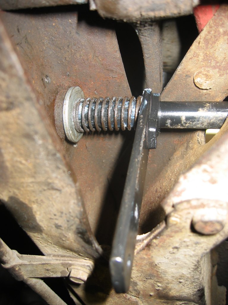 Here
on the left is the frame end of the new shaft installed. You can see the felt oil
wick against the frame. Next comes a washer. The washer was a
minor chore. The old one was pretty rusted and worn so I took a big
standard washer and shaped it to fit with my drill press and angle grinder.
The washer serves as the mount for the spring that keeps the linkage tight
so it does not rattle around. Here
on the left is the frame end of the new shaft installed. You can see the felt oil
wick against the frame. Next comes a washer. The washer was a
minor chore. The old one was pretty rusted and worn so I took a big
standard washer and shaped it to fit with my drill press and angle grinder.
The washer serves as the mount for the spring that keeps the linkage tight
so it does not rattle around. |
|
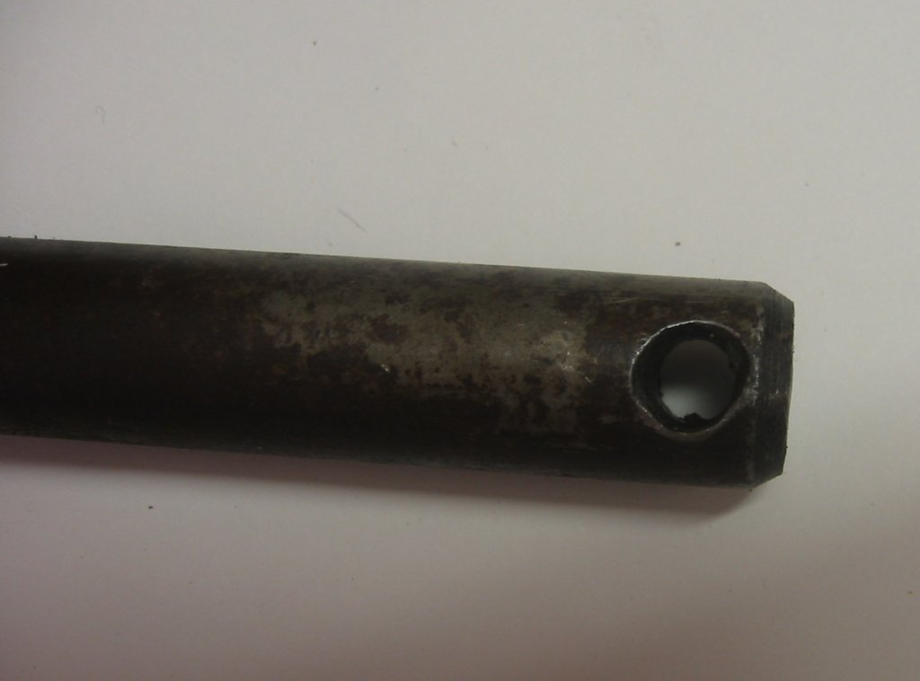
 On the right is the other side of the frame rail. You can see the hole is quite oval. I thought this was wear at first but it seems too even. If I have future problems this is an area I will check closely. Another felt oil wick and end cap enclose the end of the operating shaft outside the frame rail. The other pictures show the parts spread out and installed. At left you can see the felt oil wick "doughnut", a thin washer, the spring, and the cap. The lower right shows how all this is installed. |
|
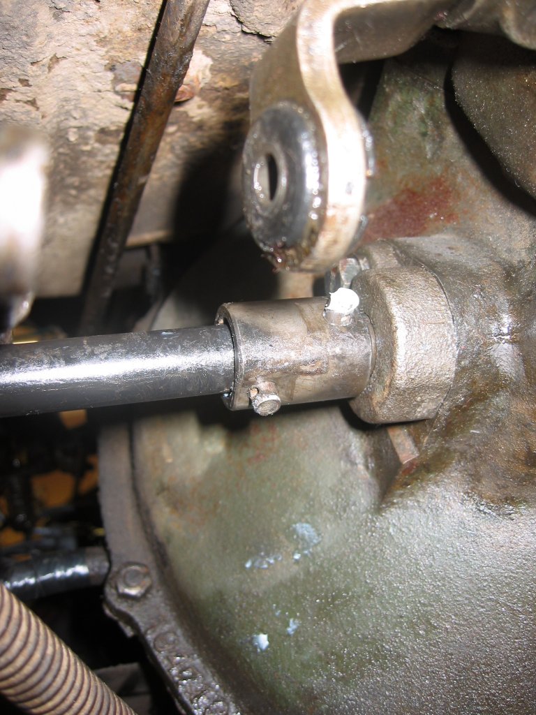  Next
I re-installed the transmission and hooked up the clutch
linkage. The picture at left shows the coupler attaching the two
shafts together. The clevis pins are in place but I had not yet
installed the cotter pins to hold them in. At right is a view looking
forward along the frame rail. You can see the turnbuckle (206-29,
206-30, and 206-32 in the exploded
view) that ties the clutch pedal to the operating shaft lever.
This turnbuckle is also how you adjust the linkage. I also have the
return spring in place that helps return the pedal to the full up position
when the pedal is not in use. Next
I re-installed the transmission and hooked up the clutch
linkage. The picture at left shows the coupler attaching the two
shafts together. The clevis pins are in place but I had not yet
installed the cotter pins to hold them in. At right is a view looking
forward along the frame rail. You can see the turnbuckle (206-29,
206-30, and 206-32 in the exploded
view) that ties the clutch pedal to the operating shaft lever.
This turnbuckle is also how you adjust the linkage. I also have the
return spring in place that helps return the pedal to the full up position
when the pedal is not in use. |
|
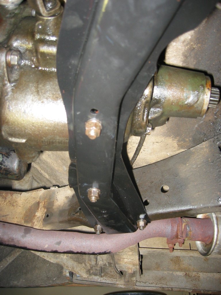 Here
I just re-installed my cleaned and painted crossmember and rear transmission
mount. The rubber in the mount seems solid enough. Amazing it
has held up so well. Once these bolts were tight I took the jack out
that has been supporting the engine. Here
I just re-installed my cleaned and painted crossmember and rear transmission
mount. The rubber in the mount seems solid enough. Amazing it
has held up so well. Once these bolts were tight I took the jack out
that has been supporting the engine. |
|
|
|
|
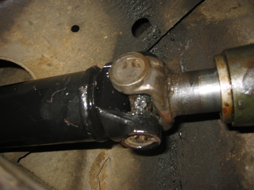 Finally
the driveshaft goes back in. Before I did this I tested the clutch by
turning the transmission tailshaft with the transmission in gear. I
could not turn it with the clutch out and could turn it with the clutch in.
Successful test! Finally
the driveshaft goes back in. Before I did this I tested the clutch by
turning the transmission tailshaft with the transmission in gear. I
could not turn it with the clutch out and could turn it with the clutch in.
Successful test!Once I got the car off the jacks I started it up and tested the clutch again. It seems good. I am nervous that I did not find a "smoking gun" that caused the clutch to fail. I sort of suspect that the old operating shaft finally wore enough to shift in the frame rail. My only other theory is that the throwout bearing got hung up on the levers in spite of the spring clip holding it in place. I don't know but I drove it 10 miles this morning (6/11/05) and it seems to work great. |
|


