Engine Assembly
5/22/2009 to 6/16/2009
  I
found the missing bit of ground strap under the bolt I
should have removed from the frame of the car. I
cleaned this up and soldered it back in. I
found the missing bit of ground strap under the bolt I
should have removed from the frame of the car. I
cleaned this up and soldered it back in. |
 Time
for the easiest points adjustment ever. Usually I am
trying to do this hanging head-down in the engine bay while
laying on the fender. Time
for the easiest points adjustment ever. Usually I am
trying to do this hanging head-down in the engine bay while
laying on the fender. |
|
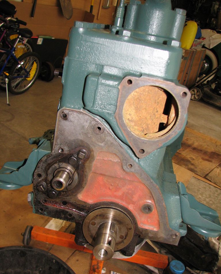
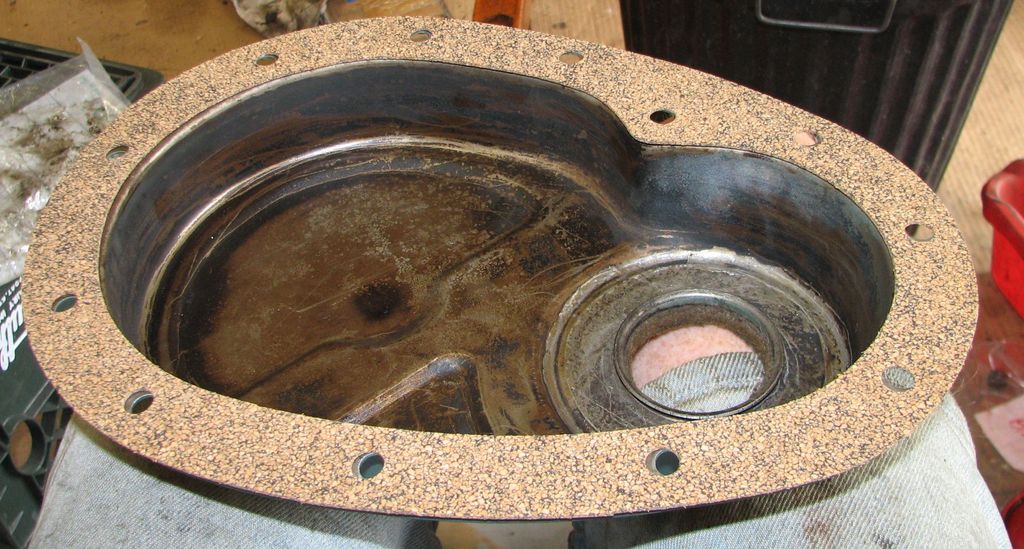
 Need
another gasket for the starter drive cover (that metal bit
in the picture). I used grease to mark the cork then
cut the gasket Need
another gasket for the starter drive cover (that metal bit
in the picture). I used grease to mark the cork then
cut the gasket |
|
|
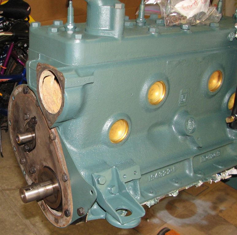
  Time
to install the freeze plugs. Nice big brass ones.
I also installed the oil dipstick tube with a 2x4. I
think it looks pretty cool Time
to install the freeze plugs. Nice big brass ones.
I also installed the oil dipstick tube with a 2x4. I
think it looks pretty cool |
|
|
|
|
|
|
 Now
it is time for the cam gear. You don't want to tap on the
cam or crank bearings so I used a bolt and an motley assortment
of hardware I had laying around the garage to pull the gear on.
I lubed everything with engine oil first. Finally I put
the cam gear bolt in with a little blue Loctite for insurance. Now
it is time for the cam gear. You don't want to tap on the
cam or crank bearings so I used a bolt and an motley assortment
of hardware I had laying around the garage to pull the gear on.
I lubed everything with engine oil first. Finally I put
the cam gear bolt in with a little blue Loctite for insurance. |
 With
the gear on I had a nice handle to turn the cam. So I
adjusted the valves to the factory spec of .016". Most
were pretty close but about 3 were too tight. That seems
odd because I would have expected them to be too loose from
wear. Adjusting the valves is very easy with the engine
out. The hardest part was finding TWO 1/2" open end
wrenches. With
the gear on I had a nice handle to turn the cam. So I
adjusted the valves to the factory spec of .016". Most
were pretty close but about 3 were too tight. That seems
odd because I would have expected them to be too loose from
wear. Adjusting the valves is very easy with the engine
out. The hardest part was finding TWO 1/2" open end
wrenches. |
 Installed
the valve covers and vent tube. The vent will have to come
off again to get the starter in. I also need to make, buy,
or steal a gasket for the vent tube. Installed
the valve covers and vent tube. The vent will have to come
off again to get the starter in. I also need to make, buy,
or steal a gasket for the vent tube. |
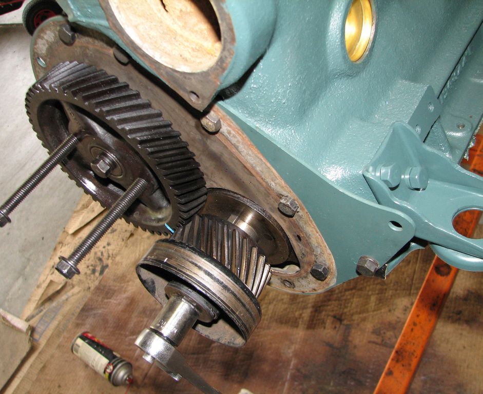 Now
that I am done flipping the cam around I can put the crank
timing gear on. The blue line highlights the timing marks
on the gears. As before I used whatever came to hand to
pull the gear onto the crank. However this time I did not
have a long bolt in the right size for the crankshaft so I had
to use the short factory bolt and make lots of adjustments.
At this point I was using an old accessory belt idler pulley for
a Chrysler minivan to move the gear another 1/4" Now
that I am done flipping the cam around I can put the crank
timing gear on. The blue line highlights the timing marks
on the gears. As before I used whatever came to hand to
pull the gear onto the crank. However this time I did not
have a long bolt in the right size for the crankshaft so I had
to use the short factory bolt and make lots of adjustments.
At this point I was using an old accessory belt idler pulley for
a Chrysler minivan to move the gear another 1/4" |
 All
timed up and ready to go. I used the two bolts and a big
screwdriver to keep things from moving while I worked.
You can see the timing mark on the cam is right between the two
timing marks on the crank gear. This means the cam is
timed and the engine is at top dead center (TDC). All
timed up and ready to go. I used the two bolts and a big
screwdriver to keep things from moving while I worked.
You can see the timing mark on the cam is right between the two
timing marks on the crank gear. This means the cam is
timed and the engine is at top dead center (TDC). |
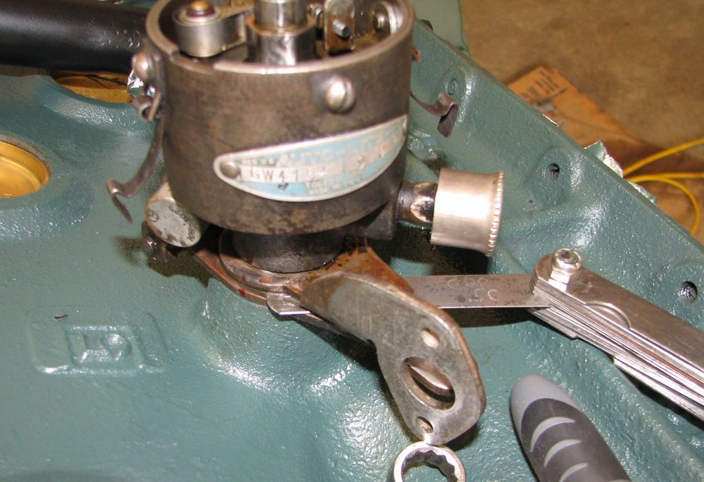 Time
for the distributor to go in. To allow the vacuum advance
to rotate the distributor there needs to be a .020" gap between
the vacuum advance mount and the arm on the distributor.
Here I am setting that gap. Time
for the distributor to go in. To allow the vacuum advance
to rotate the distributor there needs to be a .020" gap between
the vacuum advance mount and the arm on the distributor.
Here I am setting that gap. |
 I
highlighted the ignition timing mark on the flywheel with a
little yellow paint to make timing easier. I
highlighted the ignition timing mark on the flywheel with a
little yellow paint to make timing easier. |
 Here
the oil pickup tube is installed and I have started laying out
the oil pan gaskets. I put bolts in some of the holes to
help locate everything. It is no wonder Studebaker's had
lots of oil leaks. This gasket is in 4 parts (5 if you
count the front plate gasket) and all have to be sealed to the
block, the pan, and each other to prevent leaks. This is a
challenge even with modern sealants. I can't imagine
trying to do this without RTV. Here
the oil pickup tube is installed and I have started laying out
the oil pan gaskets. I put bolts in some of the holes to
help locate everything. It is no wonder Studebaker's had
lots of oil leaks. This gasket is in 4 parts (5 if you
count the front plate gasket) and all have to be sealed to the
block, the pan, and each other to prevent leaks. This is a
challenge even with modern sealants. I can't imagine
trying to do this without RTV. |
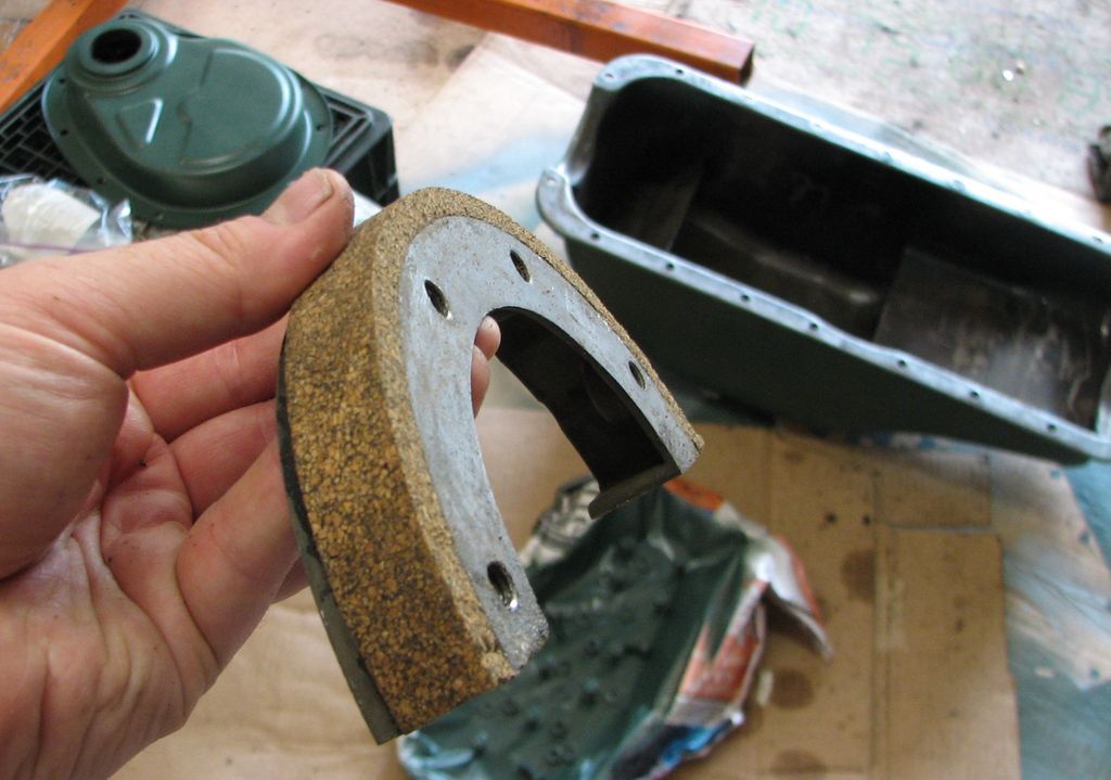
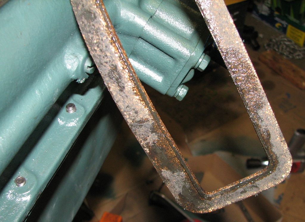
   Most
of the gaskets I got for this engine fit well. This one
does not fit well at all. As you can see on the left the
tab is too wide to fit into the grove on the rear bearing block.
As is the cork strip that is supposed to fill that groove.
And the gasket for the front filler block is both too long and
too wide. And how the hell do I hold these fat bits of
cork in place while the pan is installed? Most
of the gaskets I got for this engine fit well. This one
does not fit well at all. As you can see on the left the
tab is too wide to fit into the grove on the rear bearing block.
As is the cork strip that is supposed to fill that groove.
And the gasket for the front filler block is both too long and
too wide. And how the hell do I hold these fat bits of
cork in place while the pan is installed? |
 That
is a bit better. I trimmed the side gaskets to fit
correctly and now the holes almost line up. I think this
will be a three step process. First I will glue the side
gaskets to the block and use the oil pan to clamp them down
while the RTV sets. Next I will trim and glue the two end
gaskets to the front plate and rear bearing block. I will
have to figure out how to hold them in position while the RTV
sets up. Finally I will RTV the oil pan to the block and
gasket. That
is a bit better. I trimmed the side gaskets to fit
correctly and now the holes almost line up. I think this
will be a three step process. First I will glue the side
gaskets to the block and use the oil pan to clamp them down
while the RTV sets. Next I will trim and glue the two end
gaskets to the front plate and rear bearing block. I will
have to figure out how to hold them in position while the RTV
sets up. Finally I will RTV the oil pan to the block and
gasket. |
  Step
one is done. I put a generous smear of RTV on the block
and stuck the side gaskets on. Any that gets squeezed out
I can clean up later. Step
one is done. I put a generous smear of RTV on the block
and stuck the side gaskets on. Any that gets squeezed out
I can clean up later.
Here I am frantically trying to install the bolts before the RTV sets. On the right you can see the result. The front filler block is installed but without the cork block there is a huge gap at the front of the pan. What a train-wreck of a design. |
 While
waiting on the glue I cleaned and installed the spark plugs,
wires, rotor, cap, and wire guide. This is starting
to look like an engine again. While
waiting on the glue I cleaned and installed the spark plugs,
wires, rotor, cap, and wire guide. This is starting
to look like an engine again. |
 With
the side gaskets on the oil pan glued down it is time to get the
big cork block glued to the front filler block. RTV and a
lot of clamps should do the trick. I will trim the gasket
after the RTV is solid. With
the side gaskets on the oil pan glued down it is time to get the
big cork block glued to the front filler block. RTV and a
lot of clamps should do the trick. I will trim the gasket
after the RTV is solid. |
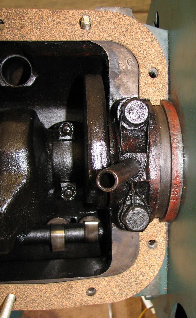
 The
rear gasket was even more fun. It was both too wide and
too long so I had to sand it down until I could "guide" it into
the slot using the thin spatula tool in the picture. Bolts
and wood wedges are keeping the block in place. I also had
to cut the cork to length and angle the ends to fit tightly
against the side gaskets. When I was happy with the
fit I RTV-ed it in place and clamped it down. The
rear gasket was even more fun. It was both too wide and
too long so I had to sand it down until I could "guide" it into
the slot using the thin spatula tool in the picture. Bolts
and wood wedges are keeping the block in place. I also had
to cut the cork to length and angle the ends to fit tightly
against the side gaskets. When I was happy with the
fit I RTV-ed it in place and clamped it down. |
 Here
is the filler block gasket trimmed. Looks pretty nice. Here
is the filler block gasket trimmed. Looks pretty nice. |
 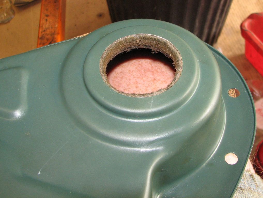 My
gasket set came with a new timing cover oil seal. On the
left you can see the old seal and the new one. The seal
was a bit of a pain to wiggle into place but I managed to get it
in there. The new seal is in the right picture. My
gasket set came with a new timing cover oil seal. On the
left you can see the old seal and the new one. The seal
was a bit of a pain to wiggle into place but I managed to get it
in there. The new seal is in the right picture. |
 The
front cover is next. This gasket fit perfectly. The
front cover is next. This gasket fit perfectly. |
 According
to the manual we have to install the crank pulley before
tightening the timing cover bolts. Here I have a long bolt
and spacer pushing the pulley in. According
to the manual we have to install the crank pulley before
tightening the timing cover bolts. Here I have a long bolt
and spacer pushing the pulley in. |
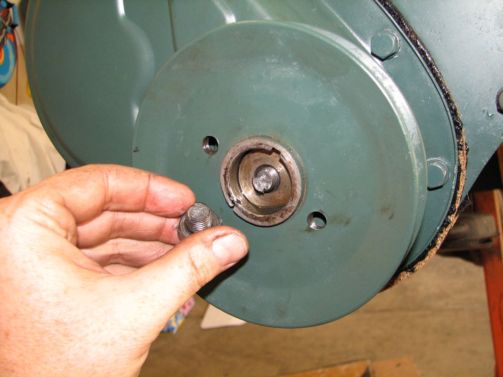 Then
I blew it. For some reason I thought the crank pulley was
supposed to be flush with the end of the crankshaft. So I
zapped it with my impact wrench. Stupid stupid stupid.
I ended up breaking off the factory bolt. Lucky for me I
have another engine. Luckier still I was able to turn the
end of the broken bolt out of the crank with my fingers. Then
I blew it. For some reason I thought the crank pulley was
supposed to be flush with the end of the crankshaft. So I
zapped it with my impact wrench. Stupid stupid stupid.
I ended up breaking off the factory bolt. Lucky for me I
have another engine. Luckier still I was able to turn the
end of the broken bolt out of the crank with my fingers. |
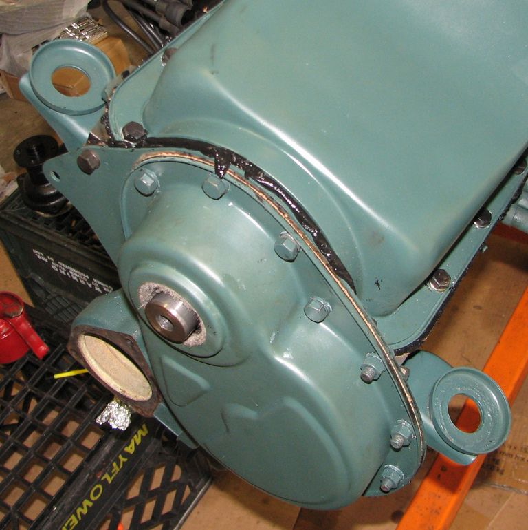
 That
is better. Of course I ended up taking the pulley off
again to install the oil pan. That
is better. Of course I ended up taking the pulley off
again to install the oil pan. |
 This
water pump bolt has seen better days. It does not look
like the hole goes into the water jacket but it sure looks like
a a lot of water has been on this bolt. Maybe years of
leaky water pumps. I replaced the bolt anyway. This
water pump bolt has seen better days. It does not look
like the hole goes into the water jacket but it sure looks like
a a lot of water has been on this bolt. Maybe years of
leaky water pumps. I replaced the bolt anyway. |
 Vacuum
advance is installed. I had to take the distributor loose
to get it in. Vacuum
advance is installed. I had to take the distributor loose
to get it in. |
 Ready
to install the oil pan. This is going to be the tricky
bit. The filler block and its gasket go on top of the side
gaskets and against the front plate gasket. Lots of places
to move and/or leak. I used the rest of my tube of RTV on
the oil pan gasket. Ready
to install the oil pan. This is going to be the tricky
bit. The filler block and its gasket go on top of the side
gaskets and against the front plate gasket. Lots of places
to move and/or leak. I used the rest of my tube of RTV on
the oil pan gasket. |
 Gee,
did I use enough? I sure hope so. If
this leaks again I will be very, very upset. Gee,
did I use enough? I sure hope so. If
this leaks again I will be very, very upset. |
 I
noticed the valve covers were leaking just sitting on the stand.
So I pulled the covers and found this. The "wet'
areas are oil. Obviously I did not use enough sealant on
the stupid thing. In fact it looks like I hardly used any.
I gave up and glued the suckers on with RTV. I
noticed the valve covers were leaking just sitting on the stand.
So I pulled the covers and found this. The "wet'
areas are oil. Obviously I did not use enough sealant on
the stupid thing. In fact it looks like I hardly used any.
I gave up and glued the suckers on with RTV. |
 Water
pump installed. The pulley is just stuck on there
for fun. Water
pump installed. The pulley is just stuck on there
for fun. |
 Fuel
pump installed. Fuel
pump installed. |
 Oil
filter installed. I just cleaned this up. It was
installed about 25 years ago from a NOS kit so all the decals
are perfect. Oil
filter installed. I just cleaned this up. It was
installed about 25 years ago from a NOS kit so all the decals
are perfect. |
 Generator,
pulleys, belt, and fan are installed. I am not sure about
my snazzy two-tone generator. If it bugs me I can always
paint it better later. I used some blue Loctite on the fan
bolts just to be safe. Generator,
pulleys, belt, and fan are installed. I am not sure about
my snazzy two-tone generator. If it bugs me I can always
paint it better later. I used some blue Loctite on the fan
bolts just to be safe. |
 Before
installing the ground strap I sanded the area it mounts to down
to bare metal. I will have to check to make really sure I
have a good ground all over the engine. A bad ground is
something to watch when everything is painted. Before
installing the ground strap I sanded the area it mounts to down
to bare metal. I will have to check to make really sure I
have a good ground all over the engine. A bad ground is
something to watch when everything is painted. |
 Before
installing the manifold I ran a die over the studs to clean the
threads. Lot of crud in there... Before
installing the manifold I ran a die over the studs to clean the
threads. Lot of crud in there... |
 Slip
the gasket on. This is much easier with the engine out of
the car! Slip
the gasket on. This is much easier with the engine out of
the car! |
 Manifold
installed! I like the brass nuts. Now I can install
all the oil, vacuum, and fuel lines that snake around the
manifold. Manifold
installed! I like the brass nuts. Now I can install
all the oil, vacuum, and fuel lines that snake around the
manifold. |
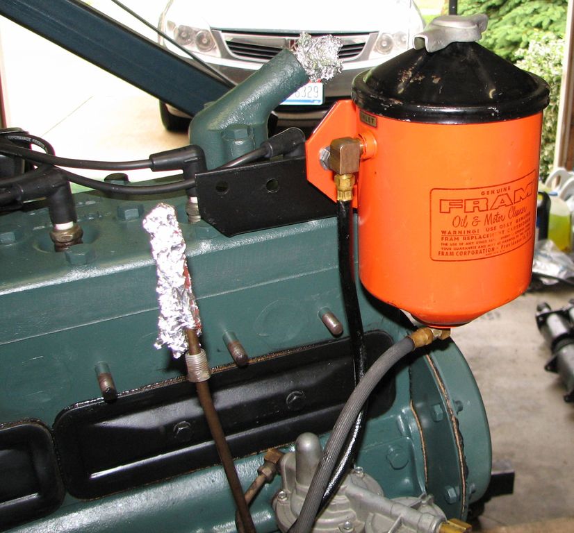
 This
is the return line from the oil filter. It drains oil from
the filter can back into the dipstick tube.
I replaced this before
and routed the line over the engine. The problem with this
is the line ran up and over the cylinder head. Since the
head is higher than the bottom of the oil filter this kept the
oil filter from draining (just like the way the s-drain in a
toilet works). So I am going to try this routing. I
made a bracket to hold the line. This might interfere with
the gas pedal linkage. I can't tell until the engine goes
back in. [Update: Turns out it works just fine!] This
is the return line from the oil filter. It drains oil from
the filter can back into the dipstick tube.
I replaced this before
and routed the line over the engine. The problem with this
is the line ran up and over the cylinder head. Since the
head is higher than the bottom of the oil filter this kept the
oil filter from draining (just like the way the s-drain in a
toilet works). So I am going to try this routing. I
made a bracket to hold the line. This might interfere with
the gas pedal linkage. I can't tell until the engine goes
back in. [Update: Turns out it works just fine!] |
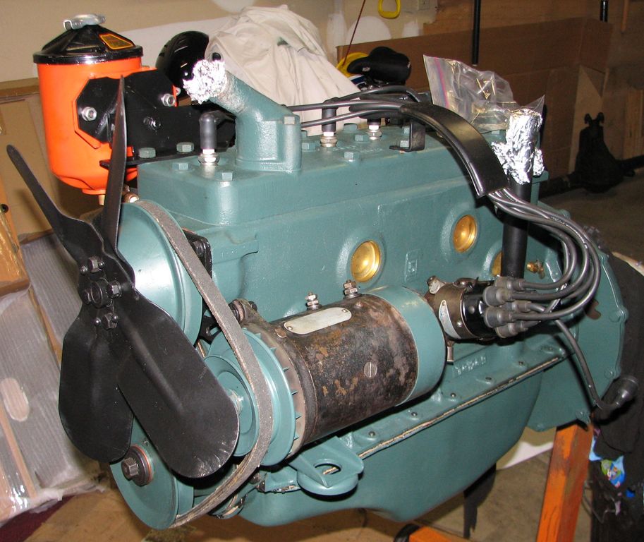
 To
wrap up the engine assembly I installed the carburetor and all
the oil and vacuum lines. Just for fun I polished all the
copper lines then painted them with clear lacquer. They
look really nice. I think the engine is ready to go! To
wrap up the engine assembly I installed the carburetor and all
the oil and vacuum lines. Just for fun I polished all the
copper lines then painted them with clear lacquer. They
look really nice. I think the engine is ready to go! |