Disc brake conversion part 2

It took longer than I hoped to get to it but I finally got moving again on this conversion.

Step one is to press the studs into these backing plates.
A large socket in the press worked great for this.
So, that was the easy part. Now it gets messy.
Car is in the air, time to pop it apart.
Say goodbye to the drums! I am doing one side at a time.
The old brakes and backing plate need to go next.
Disconnecting the brake line from the flexible brake hose.
I don’t recall how I removed this clip last time I did this but this way worked super well.
These 4 bolts hold the backing plate on.
And off it comes!
I cleaned up the spindle, everything looks ready to go here.
This is the bracket that holds the caliper. The hardware is all grade 8 and the nuts are self-locking. I am going to test assemble this with regular nuts and make sure everything fits.

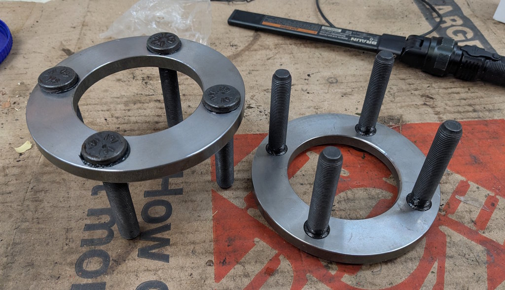
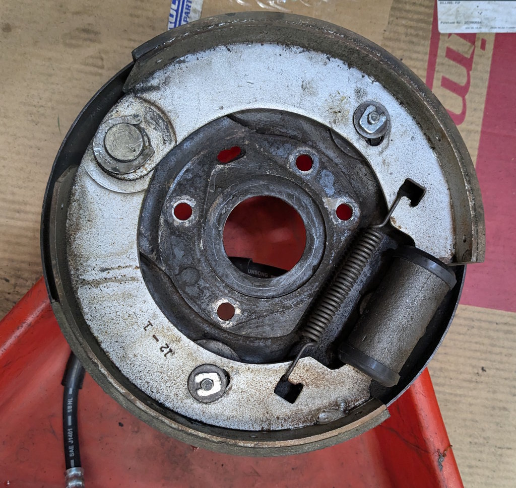
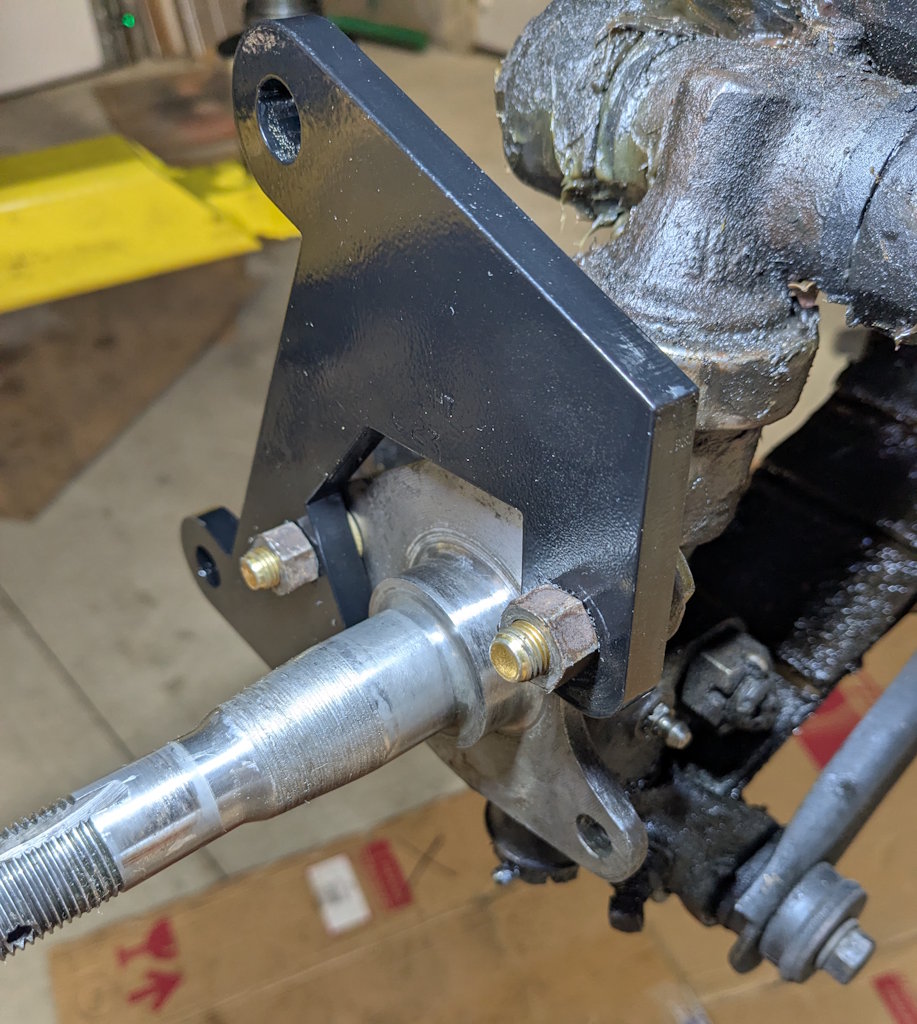
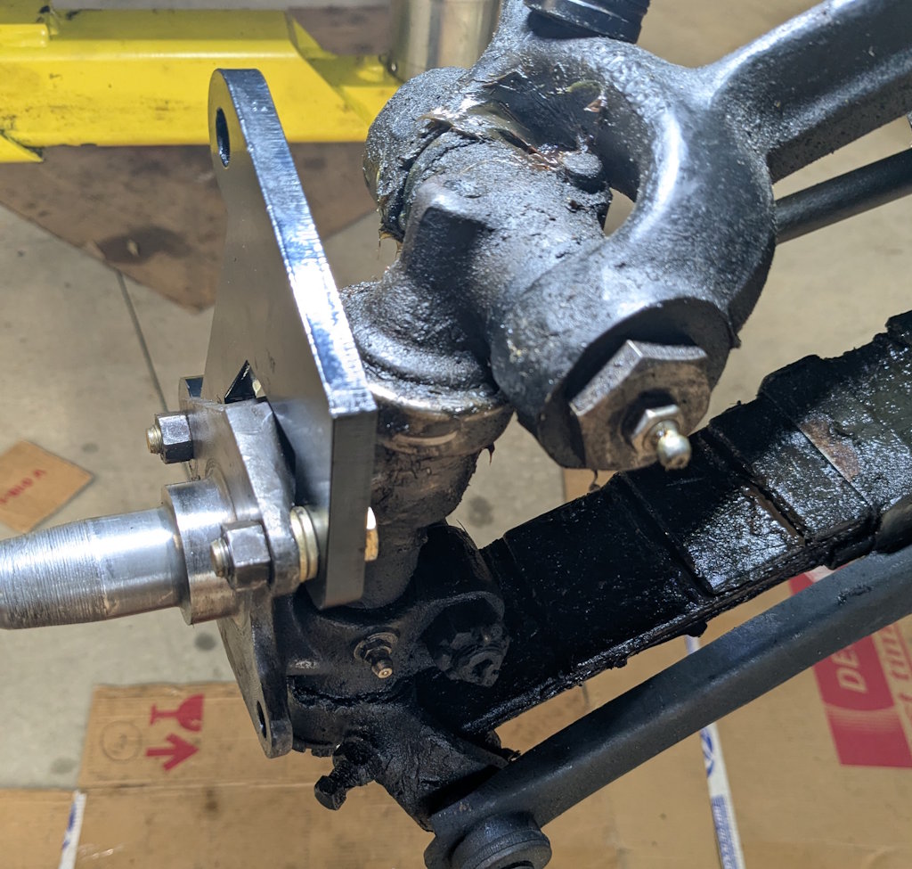
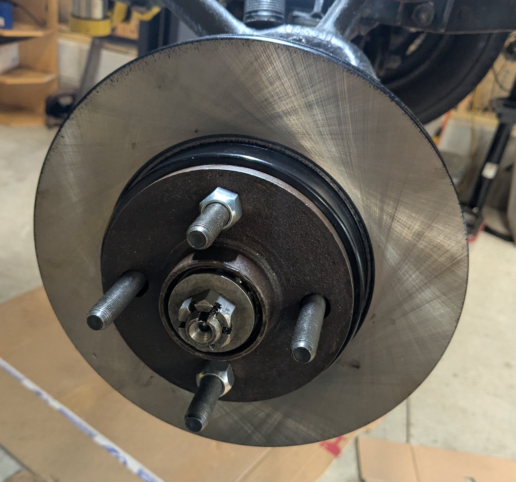
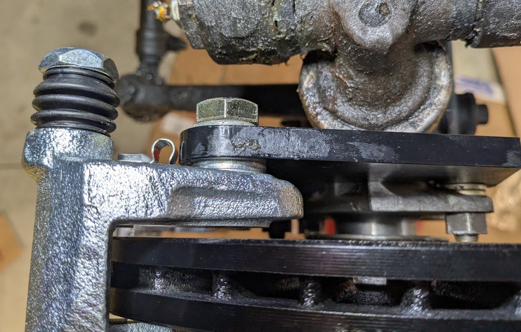
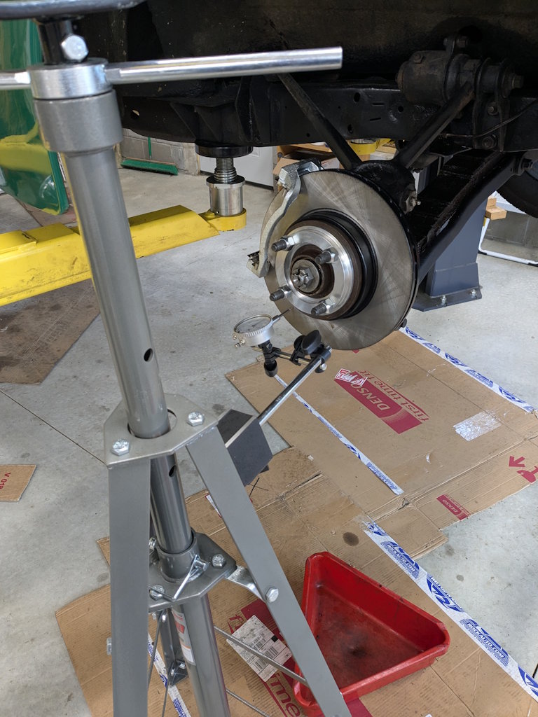
I read the instructions carefully and still managed to put this together wrong. When I tried to put the rotor on the bracket did not clear. A quick e-mail to Jim Turner cleared this up.

Here is how it really goes. There are machined round flat spots on the back of the spindle and the two lock washers fit right in. I had to use two lock washers because the bracket was hitting the top of the spindle. You can see even now it is very, very close. The instructions say you can use two lock washers but I may just file a notch in the bracket to get enough clearance to use one. You will see why later.
The backing plate, rotor, and hub stack is in place. Everything looks good here. Time to test fit the caliper.
The instructions say there is a right and a left but as best I can tell the two calipers are identical. I grabbed one at random and took the pin bolts and pads out.
The first time I test fit the caliper frame to the bracket it hit the rotor. That is because I used those two lock washers before. The kit came with two washers for each bolt so I added another one.
With two washers the spacing is perfect but the bolt is now recessed in the caliper frame, which I don’t love. I am thinking if I can shave out a set of washers all around I will be better off.
I put the caliper together and everything looks good.
Now I want to see if the wheels fit. To do that I need the adapter ring on there.
And it does! This looks really good. It is weird to see discs under this car.
Here is the other side. Not even close to the wheel.
Now I want to know how bad the runout is. This sketchy rig is what I came up with to do that. I tourqued the lug nuts and started to measure.
20 thousandths (0.020″) of an inch. That is quite a lot. Modern cars spec resurfacing or replacing the rotors if the runout is around 0.015″ and the new spec is usually 0.005″. But of course this is not a modern car. Let me see if I can make it better through re-orienting (indexing) the hub on the rotor.
And that just made it worse. I fooled around with this for longer than I care to admit and got nowhere.
I even tried filing a bit on the rusty parts on the back of the hub. That helped a tiny bit but I am not going to try and hand-machine this flat. That will never work. I knocked off for the day and sent another e-mail. The response was basically “don’t worry about it” so I won’t. But this ate up the rest of my time for today.

I need to decide what to do next. I could permenantly install the right side but I kind of want to test-fit the left just in case there is a big problem. It would be easy to put the old brakes back on at this point but once everything is torqued and has Lock-Tite on it that will be a lot more work. I should resume this tomorrow.


Leave a Reply

Your email address will not be published. Required fields are marked *