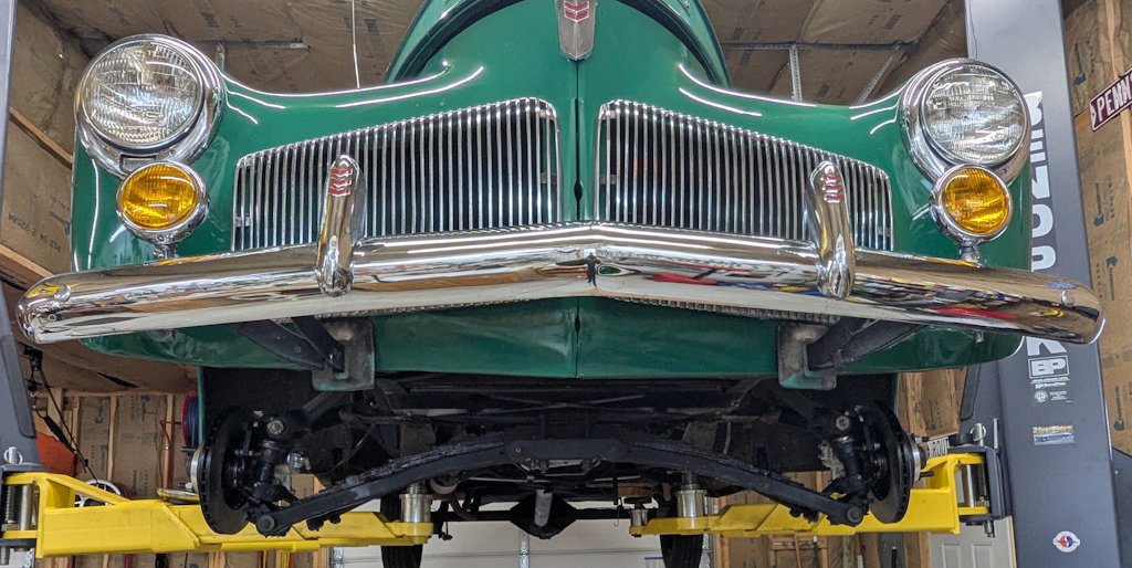
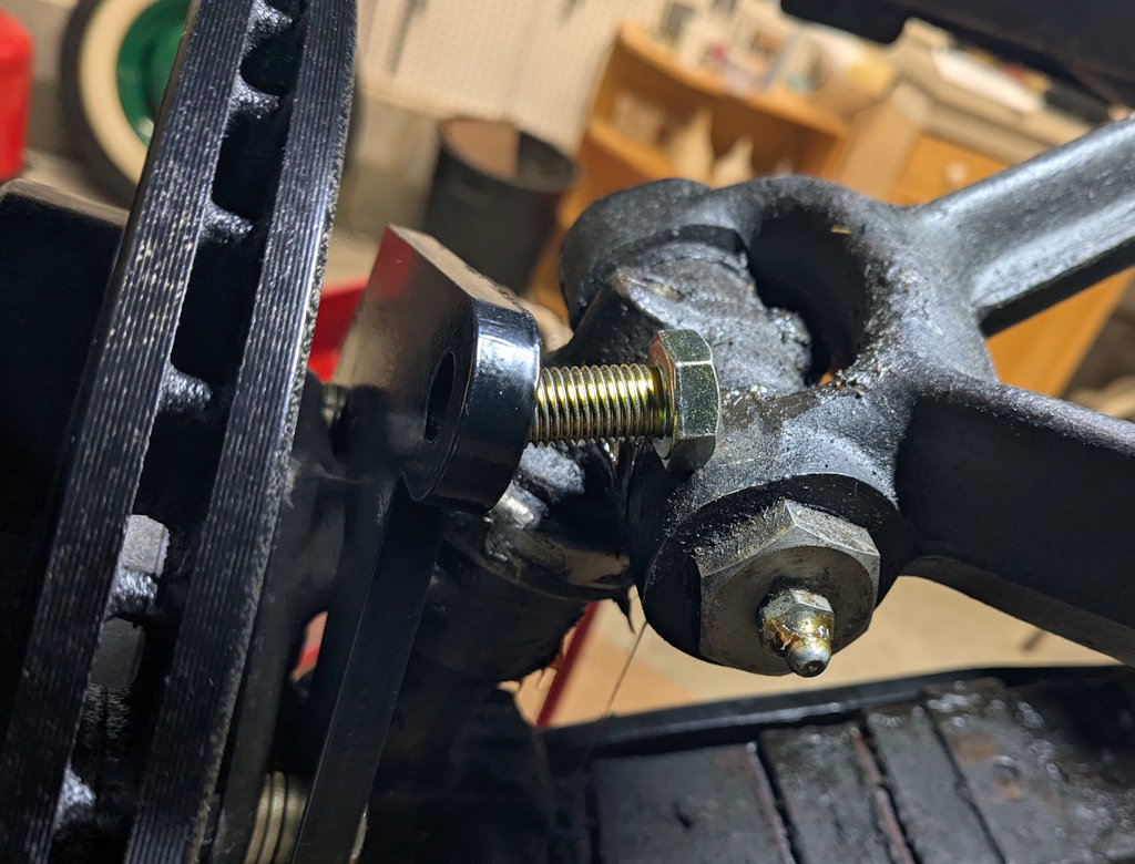
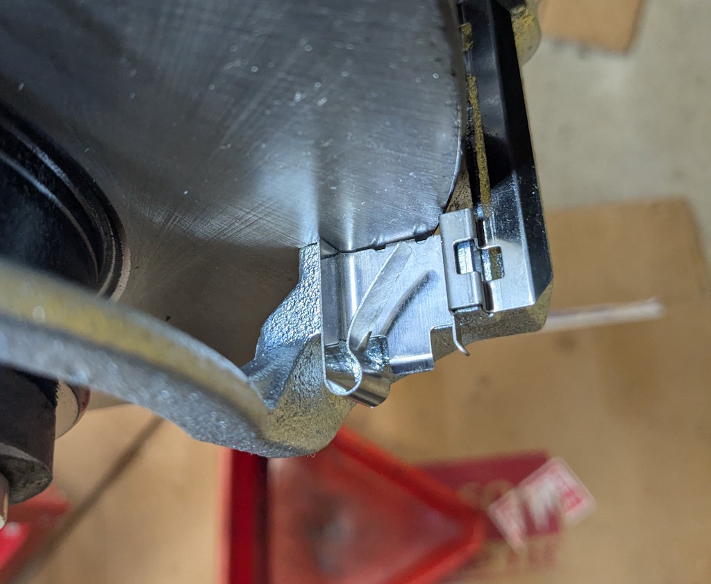
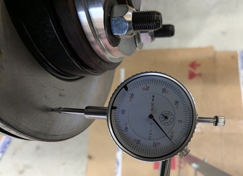
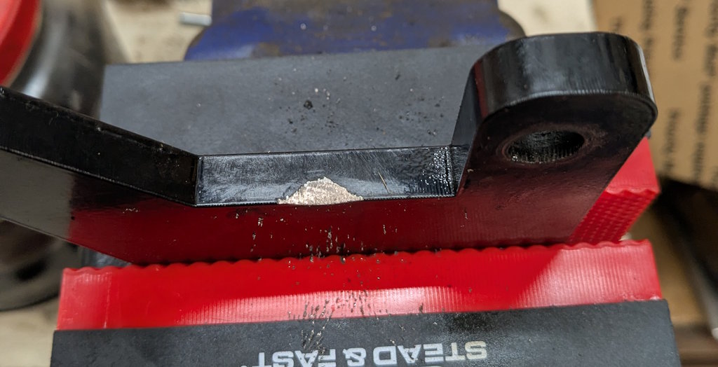
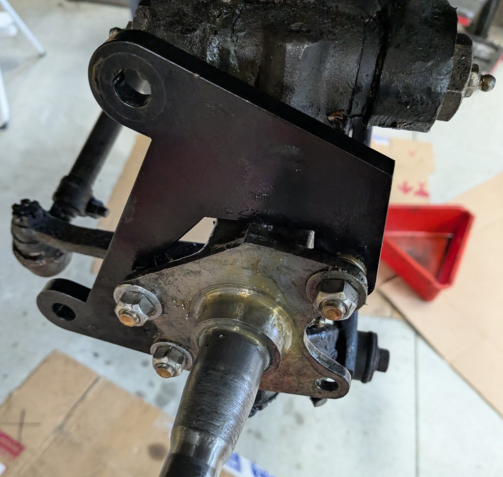
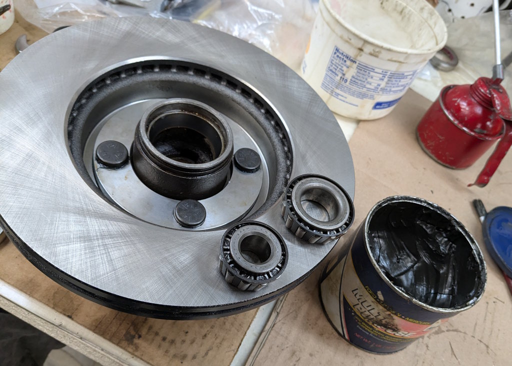
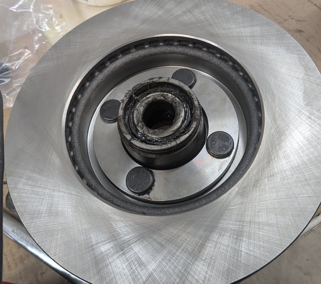
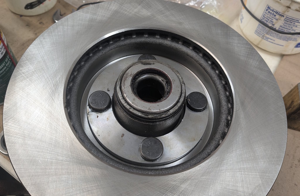
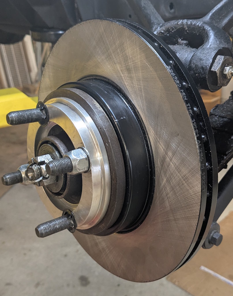
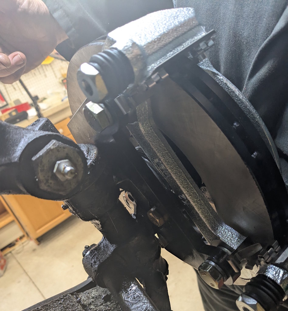
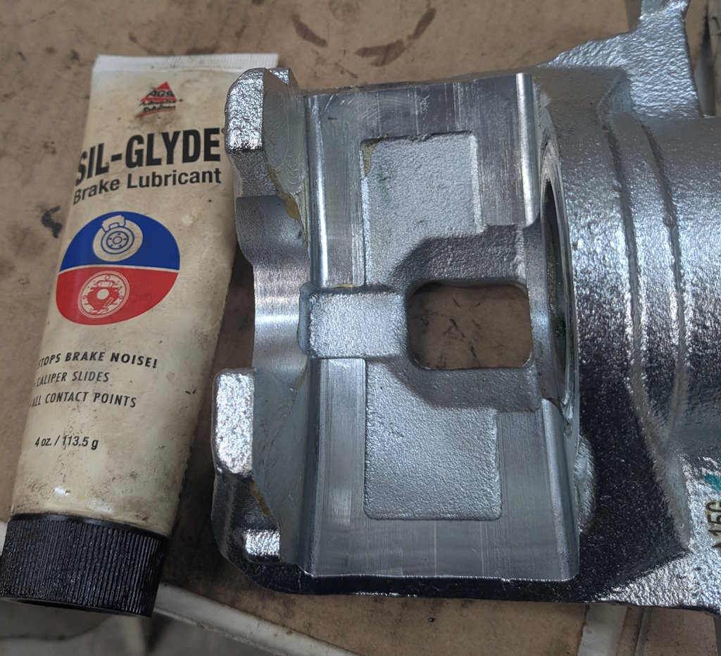
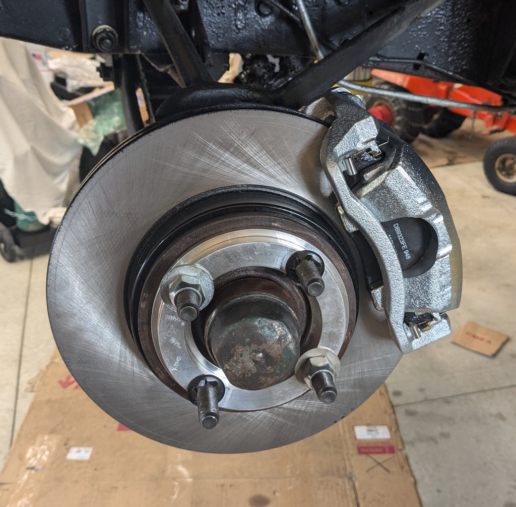
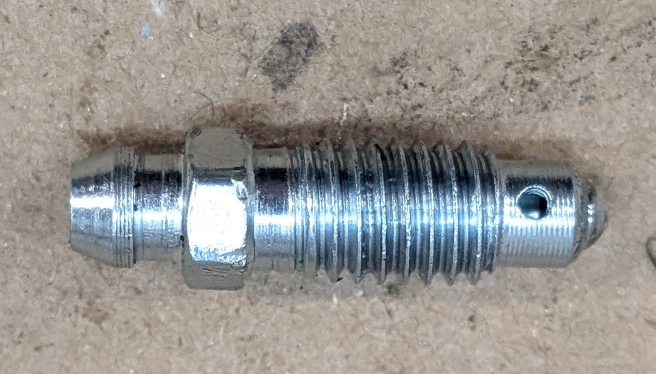
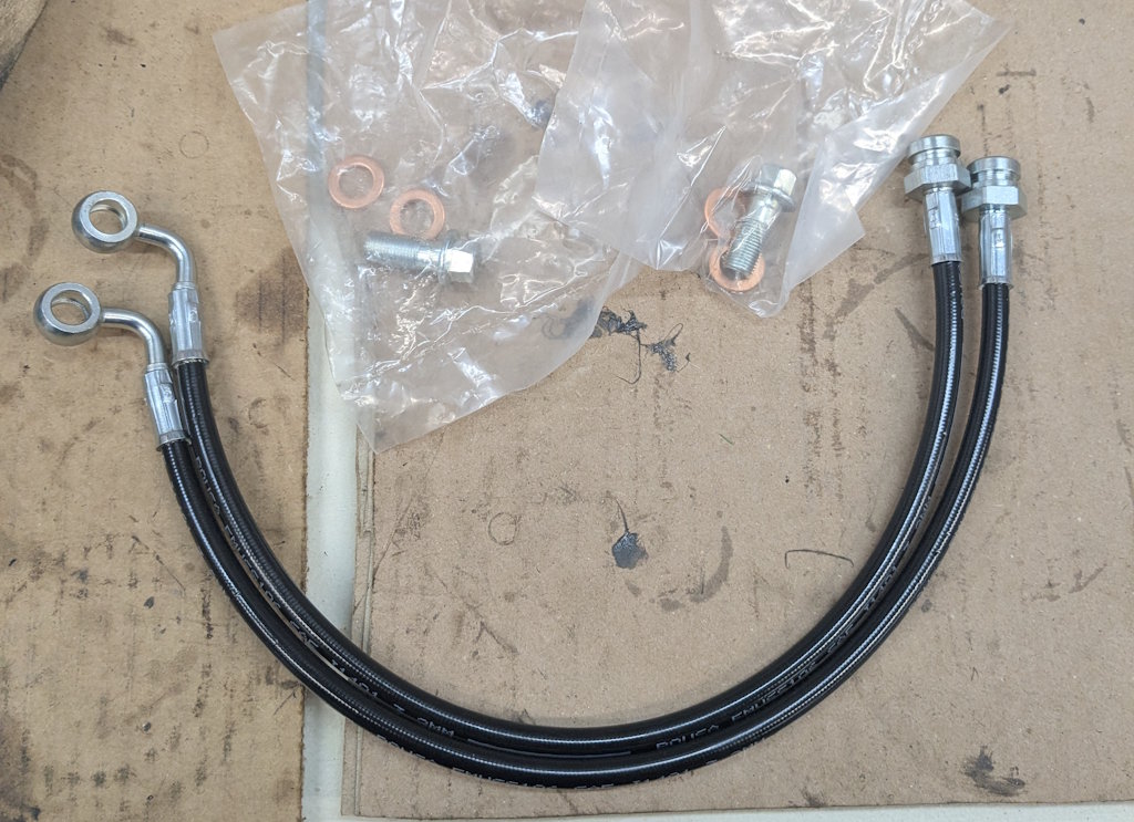
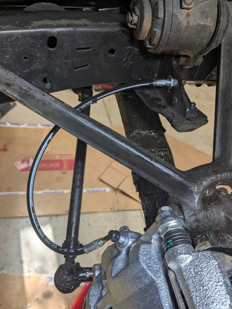
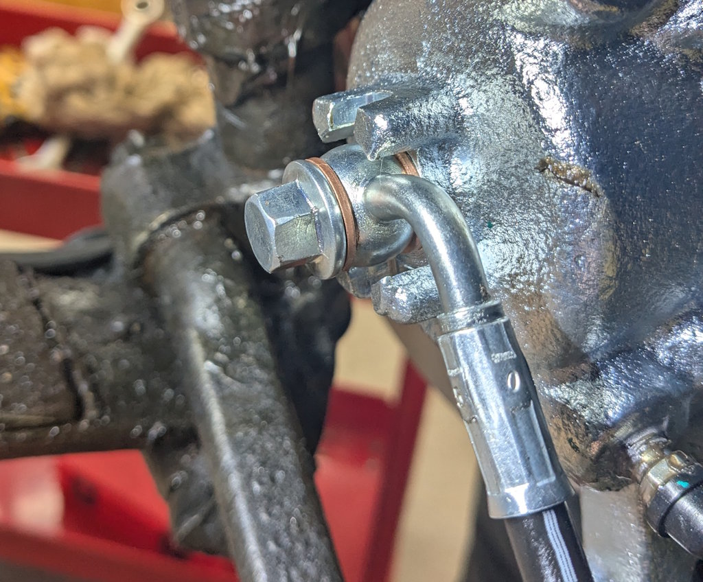
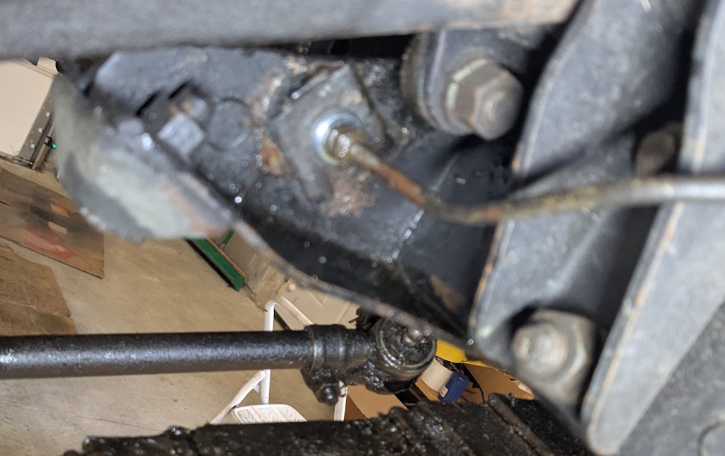
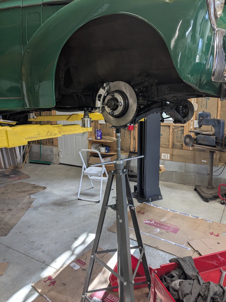
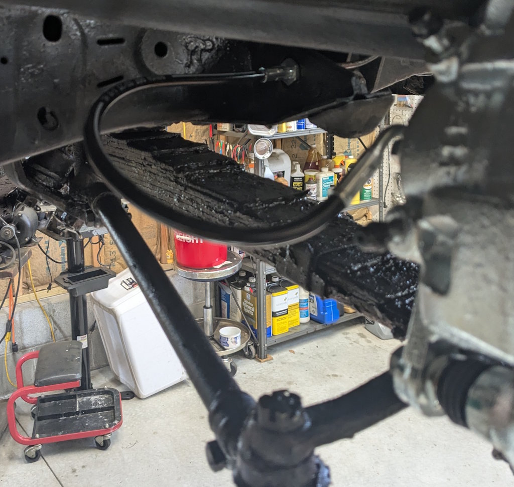
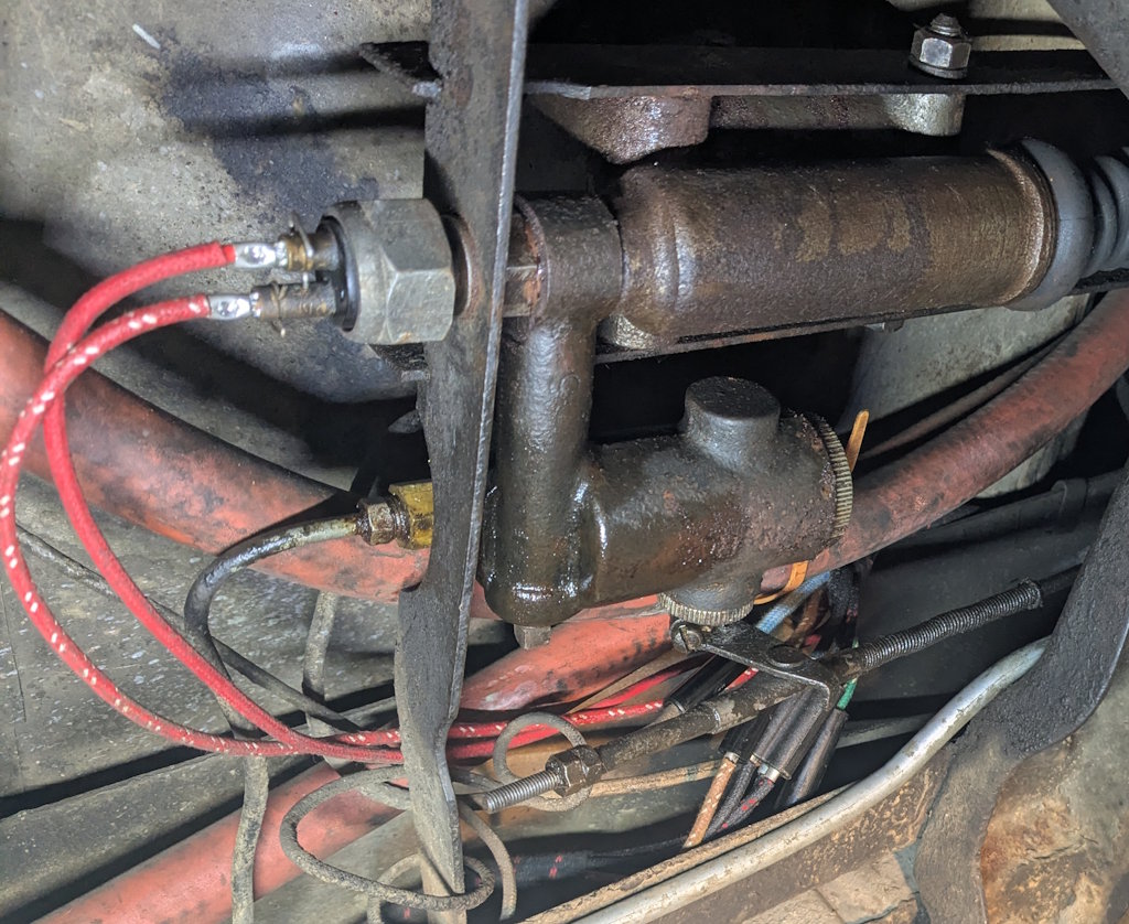
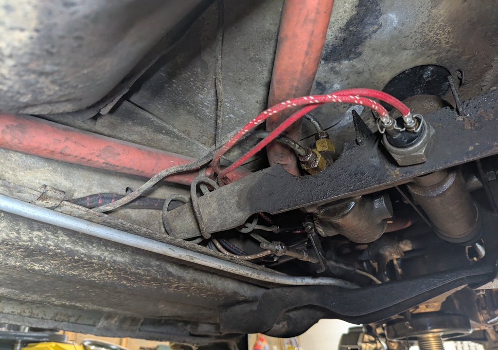
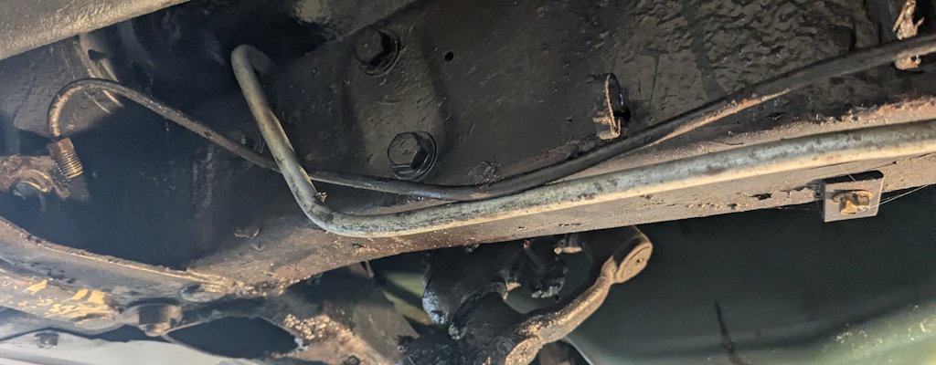
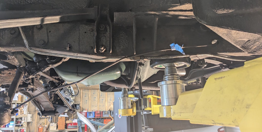
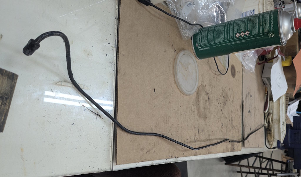
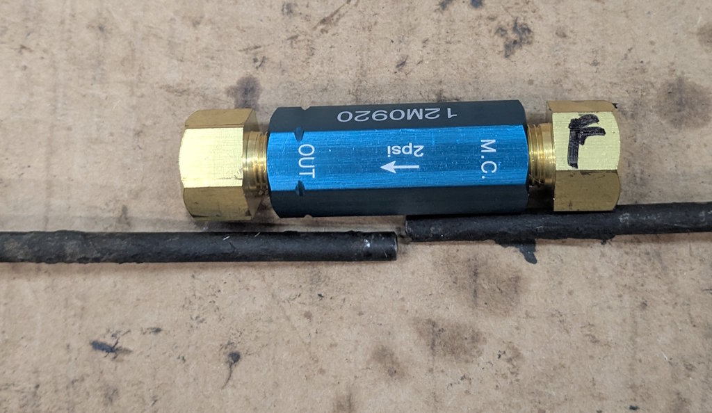
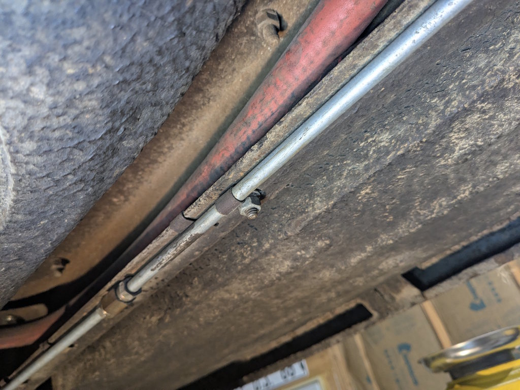
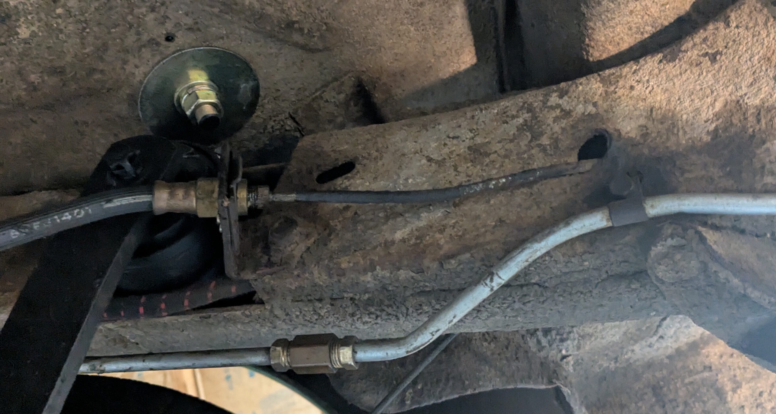
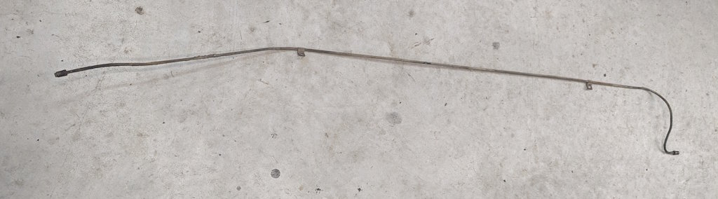
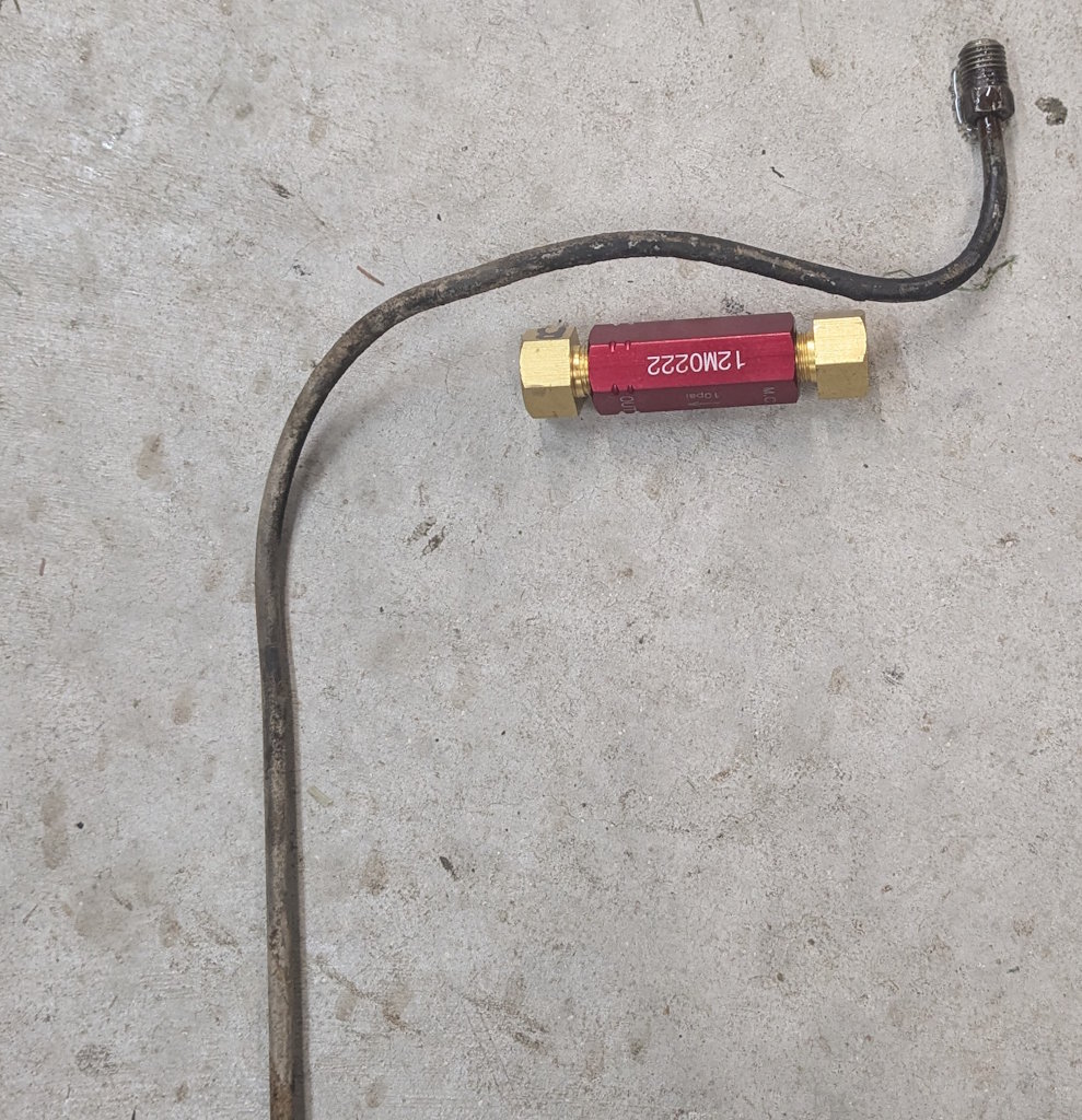
I am going to start this off with the hero shot of the front discs installed. Looks really good, but here is how we got here.First I needed to test fit the driver’s side caliper. This went just like the passenger side with a couple of snags. The first “problem” was I could not get the bolt in for the caliper rail. I started to get concerned then I remembered the front wheels on cars actually turn. That fixed the “problem”.The next problem was that the caliper rails hit the rotor. I used two washers just like the passenger side but obviously this side is different. This does not surpise me a lot. With no CNC machines every machining operation at Studebaker required either a manual operation or custom mechanical tooling. The spacing between the machined flats on the spindle and the face of the spindle was NOT a critical dimension, so they did not worry about it. Going to one washer centred it perfectly. More good news! When I checked the runout on the driver’s side, it was only around 0.010″, which is a lot better than the passenger side. I am almost ready to assemble the brakes “for real”. First, the passenger-side bracket was hitting slightly on the spindle, so I filed it down and touched up the paint. I assembled the bracket to this spindle using red Lock-Tite and the self-locking nuts that came with the kit. I torqued them to 50 ft-lbs. I put washers under the nuts because I didn’t want the nuts to damage the face of the spindle. I could not use lock washers because the bolts were too short. I don’t think it will be a problem. I also sprayed the spindle face with some anti-corrosion goop. Time to pack the bearings. This is messy and hard to take a picture with grease all over my hands. Rear bearing installed.Then I tapped the new grease seal in. I also cleaned the rotor face and put the anti-corrosion goop around the hub.The rotor was installed with a new cotter pin. The kit came with those two clips to hold the “stack” of parts together when the lug nuts are removed. Then the caliper rails bolt up to the bracket. The kit instructions said to use red Lock-Tite for this, but I used blue so I can remove the rotor without using heat. It will be fine. I lubed up the rails and caliper with brake lube.All bolted up. This looks good. Then I got to take it apart again to put the springs in. That was bad enough, but then I did the same thing on the other side!The driver’s side went together exactly like the passenger’s side, including forgetting the damn springs.The bleeder screws are 8mm x 1.5. I will probably try to find a set of speed bleeders in this size. Mechanicals are done, time to move on to the hydraulics. The kit came with these new flexible brake lines. I can only do the passenger’s side now since I need to mess with the hard lines on the driver’s side. It took some fiddling, but I eventually came up with this routing for the line.Here is how the line meets the caliper. The little “ears” on the top and bottom were probably intended to go around the hard line on the banjo union, but I could not make that work out. The focus is bad, but here is the other end clipped in place and with the brake line attached.I wanted to make sure the hose cleared the suspension, so I used a jack stand to raise it to ride height. I then turned the wheels stop to stop and checked for any problems. This is as close as it came to anything.Now the passenger’s side is complete! Looks really good. Next, I went under the car. The master cylinder needs to come out for rebuilding and modification. In addition, I need to put two residual pressure valves in the front and rear brake lines somewhere. Here is what it all looks like to start with. The front brake line comes out of the back and loops over to the frame rail to run backwards. The front brake line comes out of the top and goes over the orange heater hose, then runs forwardHere is another view. What looks like a leak is actually some penetrating oil I put on the fittings. It is not leaking. Here the brake lines have been removed, as well as the brake light switch. That and a single bolt forward are all that hold the master cylinder in. I removed the cotter pins holding the brake rod and hill holder rod, then removed the master cylinder. The brake rod is just being held on by the rubber boot at this point.The front brake line is snarled up with the fuel line. With a little wiggling I was able to get the front part of the brake line hanging loose. The blue tape is marking where I think the residual pressure valve will go. At this point, I was stuck. I could not get the line the rest of the way out. So, I cut it at the taped mark.The cut line came right out. Here is the pressure valve next to the cut line. I will just need to trim the line to length and put new flare fittings on the ends.The rear line runs inside the frame rail. That clamp holding the fuel line has an identical clamp on the inside using the same bolt. The wiring harness and heater hose run in front of the brake line.At the arch over the rear axle the line goes through the frame rail and connects to the rear flex line. I figured it was worth a shot to remove the line. I popped off the clips holding the wiring harness and slid it out of the way. Then I disconnected the clamps and the flare fitting at the rear. To my surprise the line slid right out.This is as easy as a brake line gets. Front is to the right. I am trying to decide where to put the rear residual pressure valve. I like this spot, except it is very close to the fitting and in a crowded spot.This is another option. I would need to bend the line a bit to separate it from the frame rail. My major concern here is that the valve will be hard to see and check for leaks. I will need to decide later since I am out of time for tonight. I did buy some fittings and an 8″ length of brake line. I should be able to make something work from that.