I hit some roadblocks yesterday and today. First, it was really, really cold. My shop is insulated but not heated. When the temperature hits single digits. it gets chilly in there. But I am getting ahead of myself.
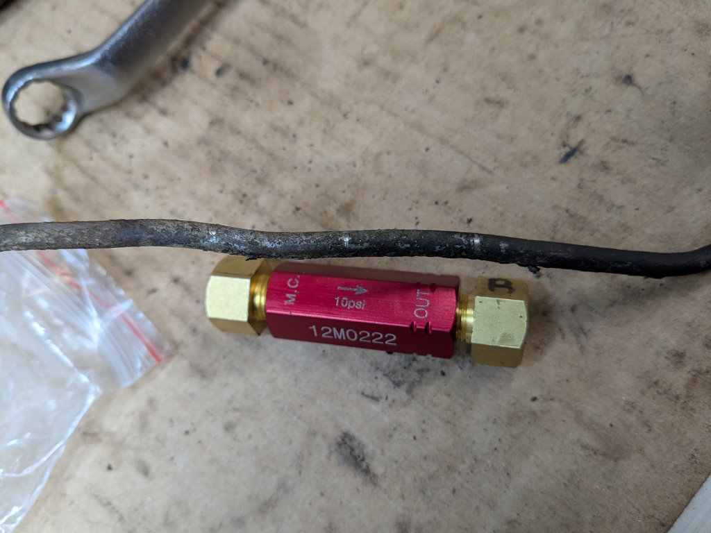
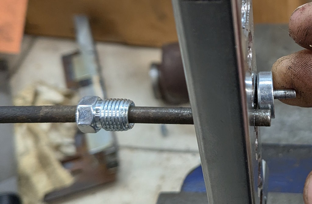
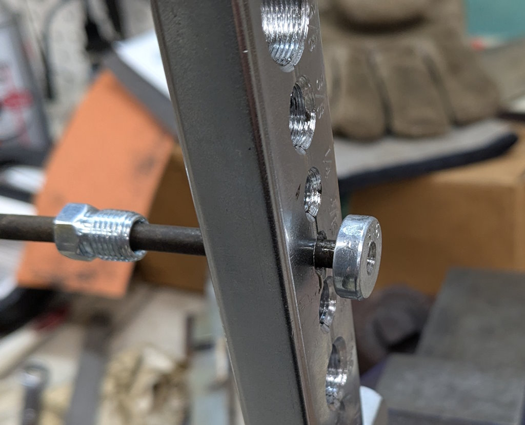
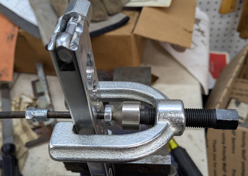
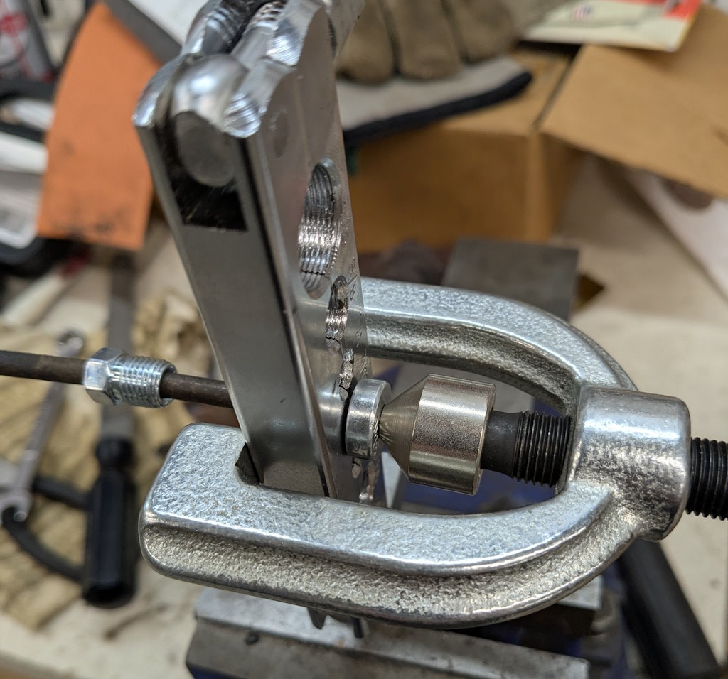
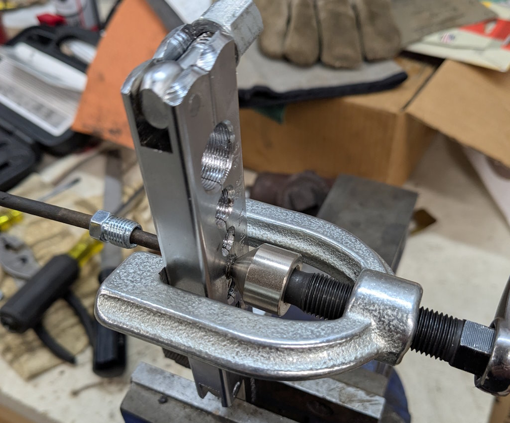
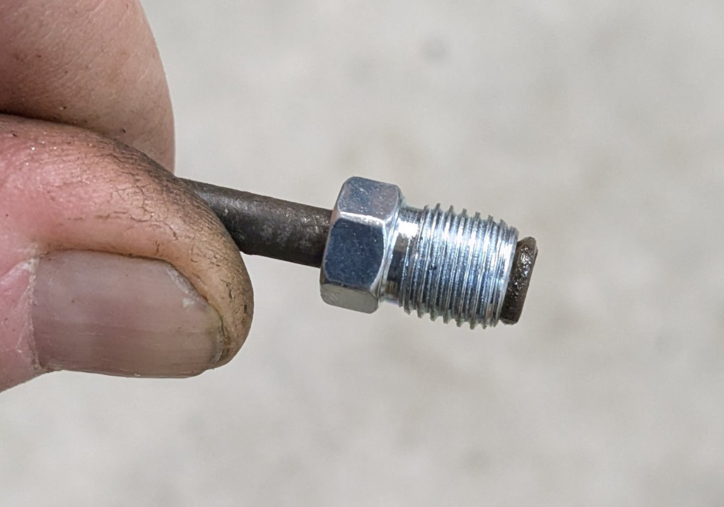
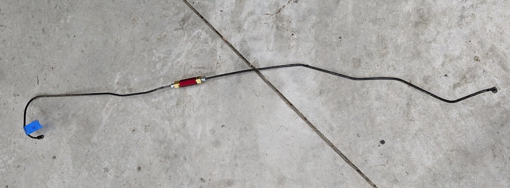
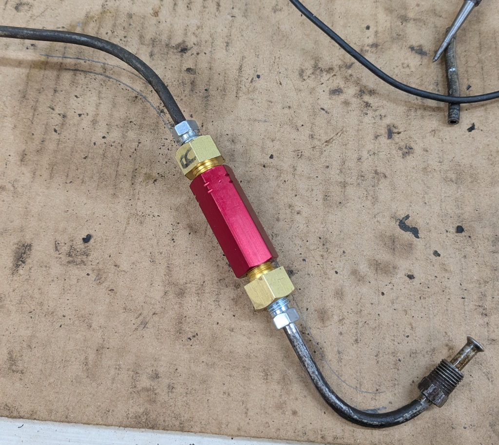
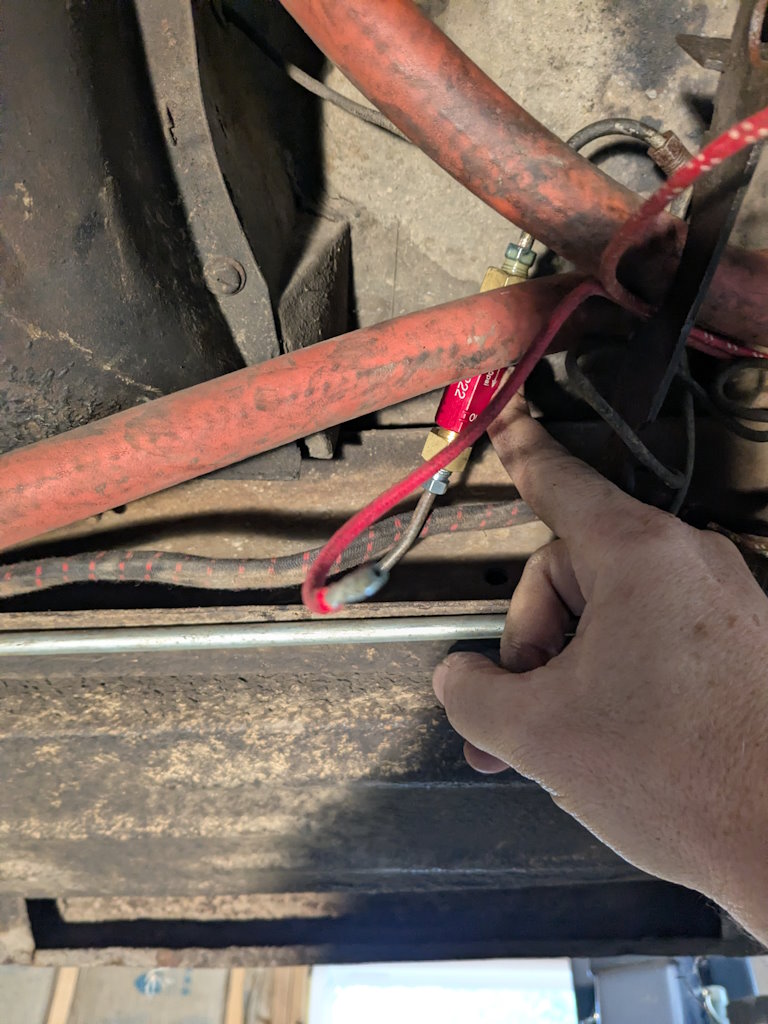
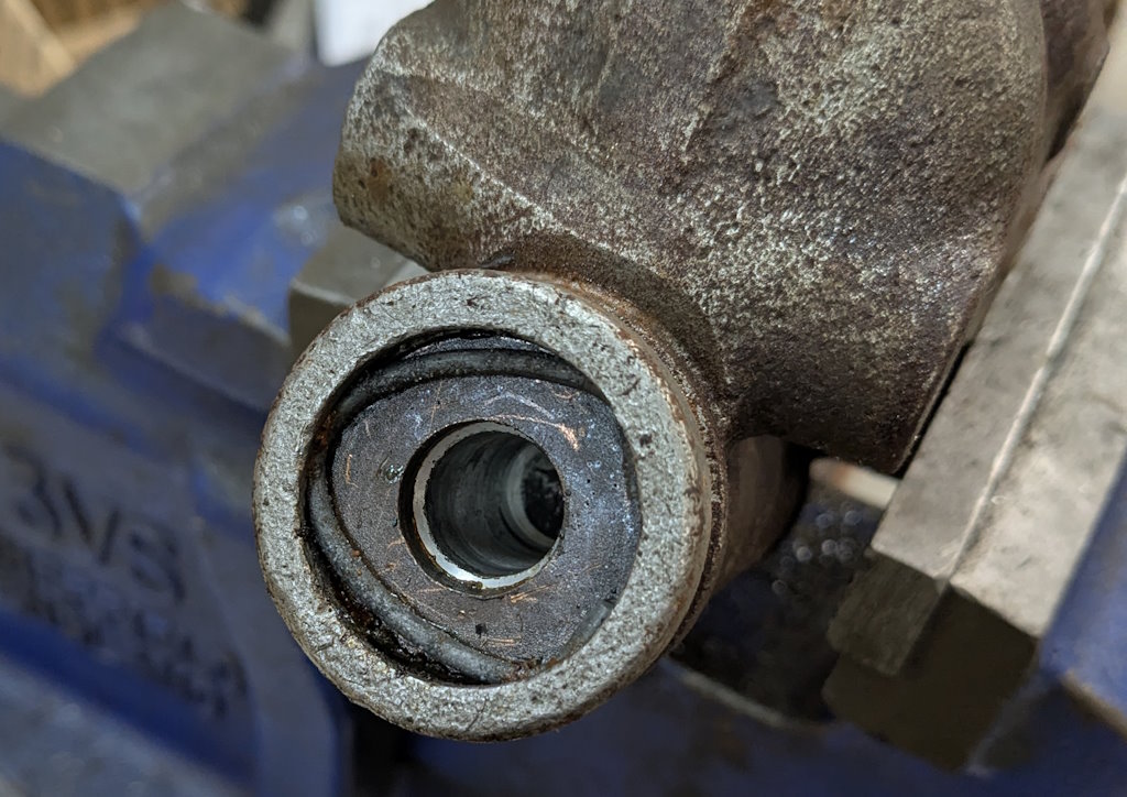
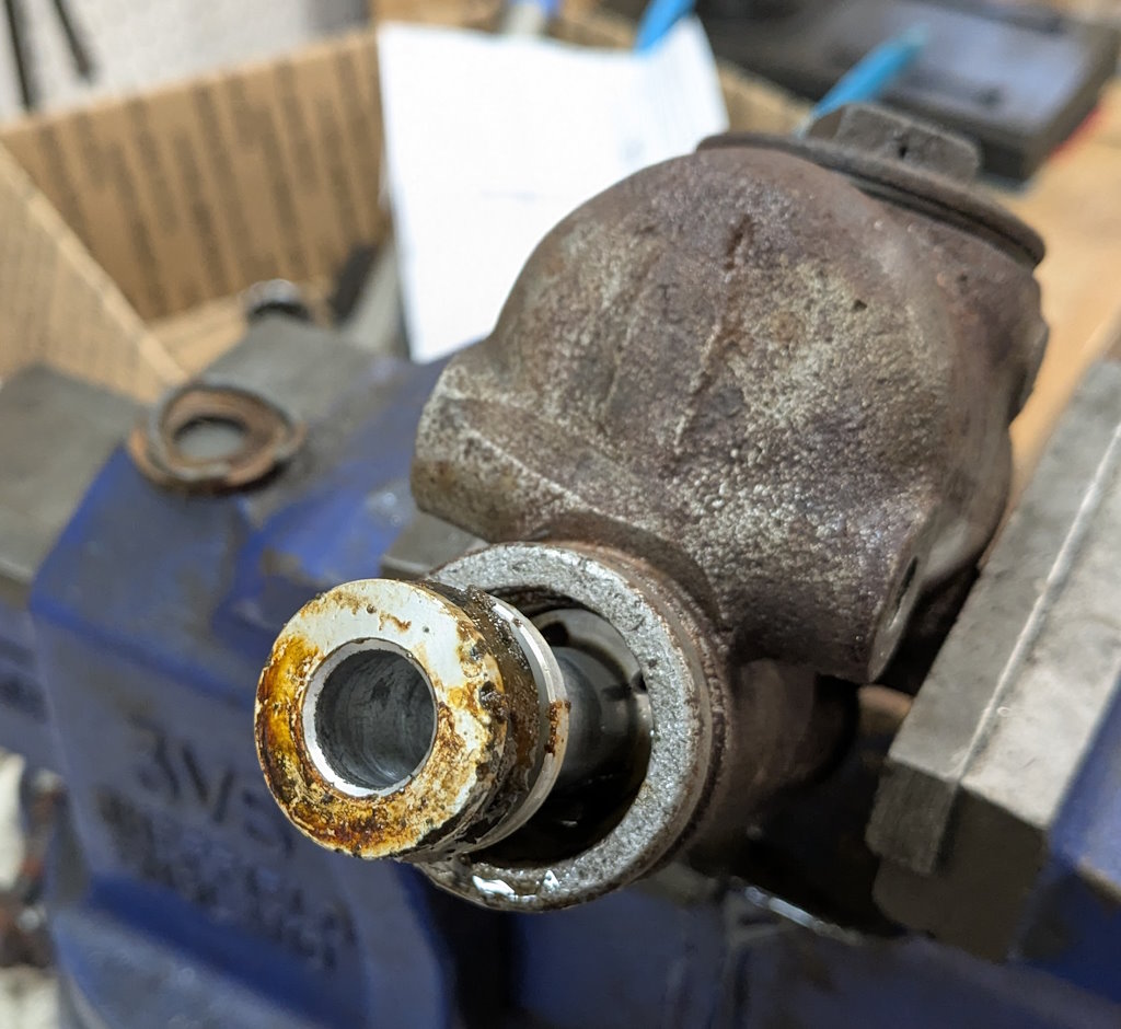
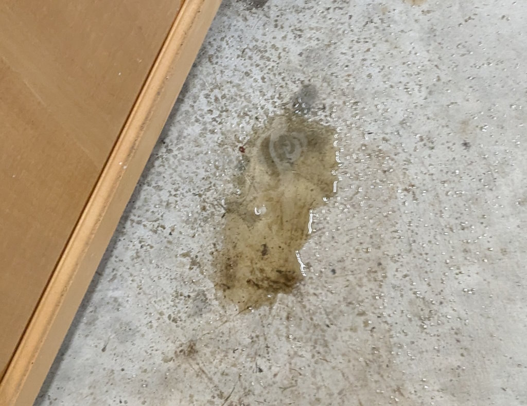
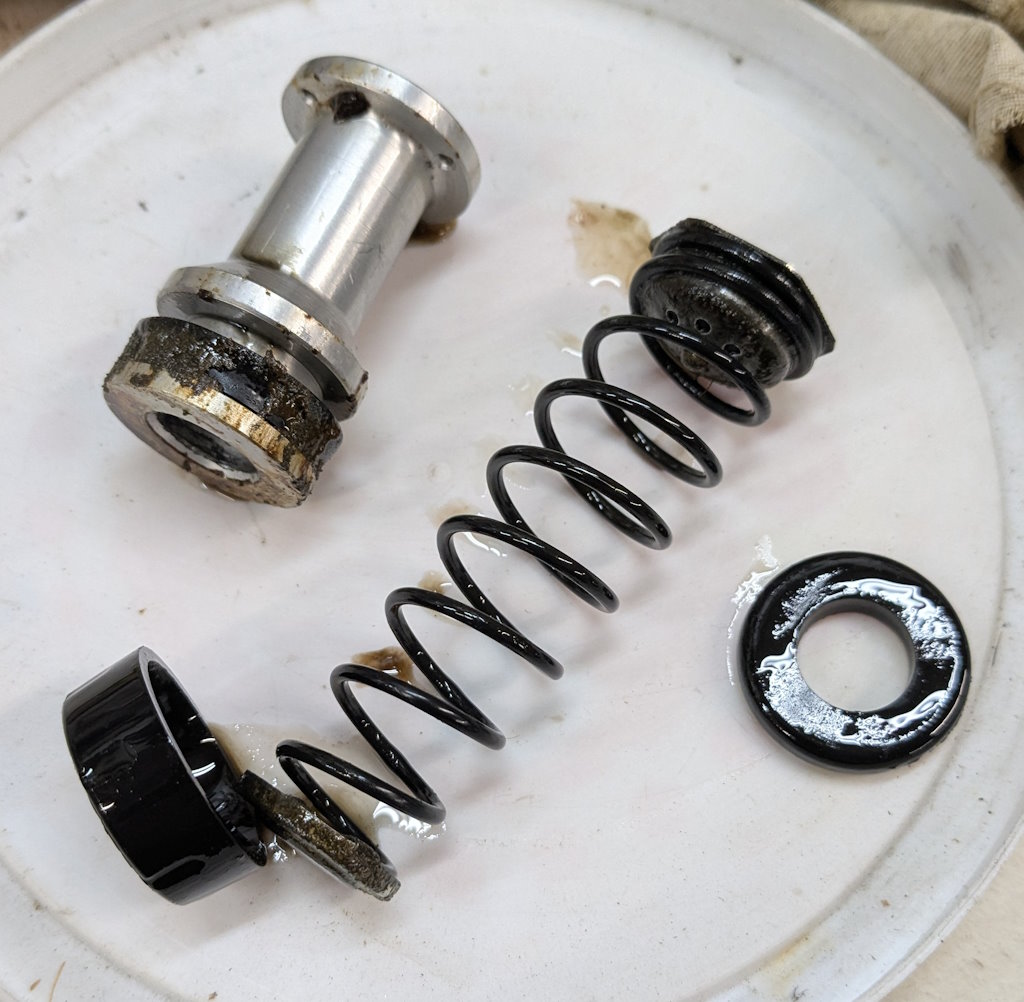
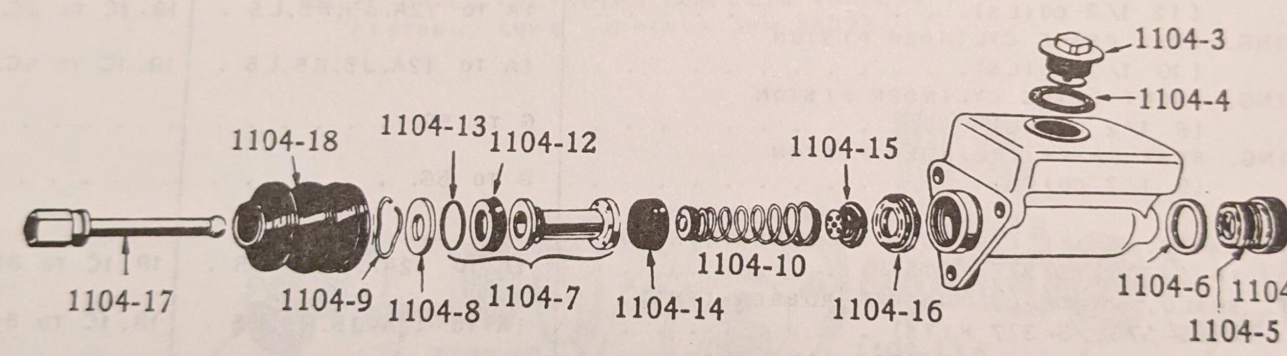
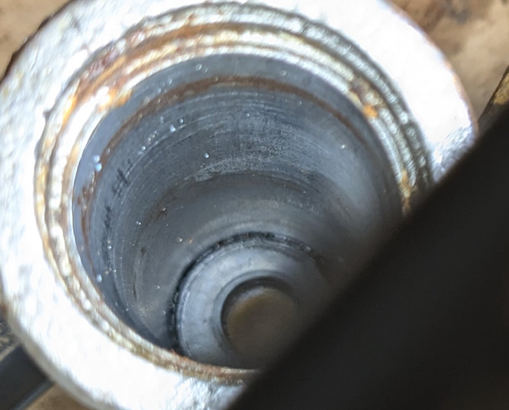
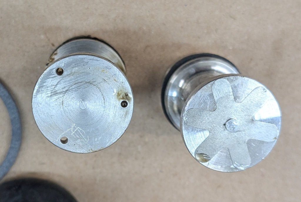
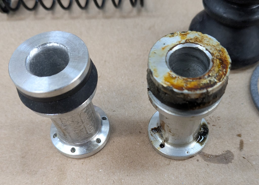
I need to fit the inline residual pressure valves into the existing brake lines. I measured carefully and did the math for the cuts. Then measured again, did the math again, and got a different answer. This is a classic measure twice, cut once situation. You can usually tweak a too-long brake line to fit, but nothing will help a too-short line. These scratch marks are my final answer. The middle one just marks the center. The outer ones are where I cut.I am going to put double-flares on these. The existing ends on the lines appear to be single flares, but the fittings on the pressure valves look to be designed for double flares. After cutting the line, it needs to be deburred. Then we are ready to flare. The first step is to put the fitting on the line. The second step is to make sure the fitting is facing the right way. The third step is to have the tube sticking out of the clamp by the width of the base of the 3/16″ die (these are 3/16″ lines).Fourth step is to check that the fitting is on the line again. The fifth step is to put the die into the end of the tube. I like to put a little oil on the face of the die.Sixth step is to put the press yoke on, centered on the die. The seventh step is to check that the fitting is on the line one last time. I am serious about this. If I do 10 of these, I will forget at least once. Squish it down. If you forgot the fitting, it is too late now. Finally, remove the die and squish it again with the press.And boom goes the dynamite! Three more to go!Here is what the front brake line looks like with the pressure valve loosely installed. Yes, this is the wrong valve, the 2 lbs valve needs to be here. I just had this one handy. I elected to put the valve in the rear line close to the master cylinder. Here is what that looks like. If you look closely, I traced the original line on the cardboard to make sure I got the length right. I think it worked out well. The short end is actually way too short to bend. But this was bent already, so I can get away with it.I reinstalled both lines. I am sure they will need some tweaking, so I did not clamp or clip anything in place yet. Now it is time to rebuild the master cylinder. To do this, push the piston in (I use a big Phillips screwdriver), then pop the spring out with a screwdriver. Then carefully release the spring pressure.Then this happens. If the MC is corroded or contaminated, the piston may stick. In that case, put a rag or something over it, because it will launch itself across the room or into your face. It helps to drain the fluid out first. I made a big mess on the floor because I failed to do this.Here are the internal parts of the master cylinder. I last rebuilt this thing almost exactly 8 years ago. The parts are still in decent shape. You can see some corrosion damage on the aluminum piston, but all in all, it held up well. Here is an exploded diagram from the parts book to orient you. This has some parts that are not in my master cylinder.Brake fluid absorbs water over time and eventually will start causing corrosion inside the brake system. I change the brake fluid every couple of years, and that seems to have paid off. The bore looks very good. Those particles in there are drops of brake cleaner, not debris of any kind.Now here is where things got strange. I purchased this kit from the same vendor I bought the last two from (admittedly 8 and over 20 years ago). But this one is different. It did not include a new spring or the rubber washer that goes at the bottom of the piston bore (1104-10 and 1104-16 in the diagram). And the piston does not have any holes in it. Every other piston I have ever seen has these little holes in the face. I have no idea what they are for.
But the back side has 6 holes in it, but they do not go all the way through. Strange.
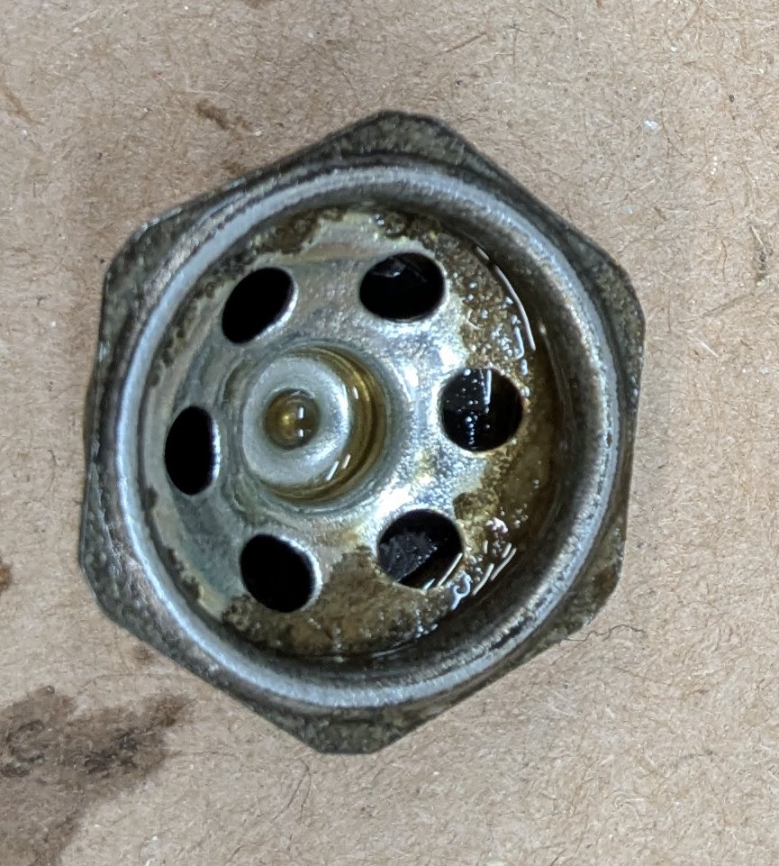
This is then residual pressure valve, which we need to not use in the rebuild. It is two cones of metal with a rubber valve between them. I think it works like the check valve in an oil filter. But the two parts below are what came with the new kit. One metal cone with fingers on the back and a strange rubber washer. I could not figure out how to put these two together to get anything that looks like it would be a valve. The rubber washer up above was the one that was in the MC before.
I decided to ask around before I commit to putting the new piston in. I am not sure what else I can do, I have some old pistons that are decent, but I am not confident I could move the rubber sealing ring without damaging it. Besides, I am running out of time for today.