The brakes are neither self-centering nor self-adjusting, so every few months I get to dick around trying to adjust the brakes so the car stops straight and has a nice firm pedal. I have been keeping my eyes open for an Ammco 1750, which will make the job a lot easier. But they are expensive. I picked up the body of the tool a couple years ago but it was missing all the parts to make it useful. Finally, about a month ago I managed to pick up a very rough but complete 1750 for about $200. The plan is to make one good one.
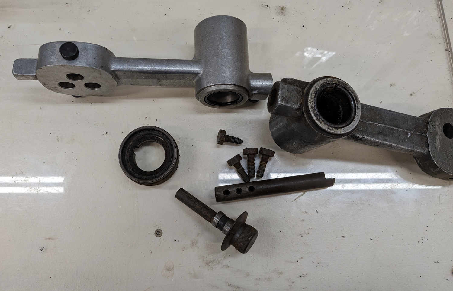
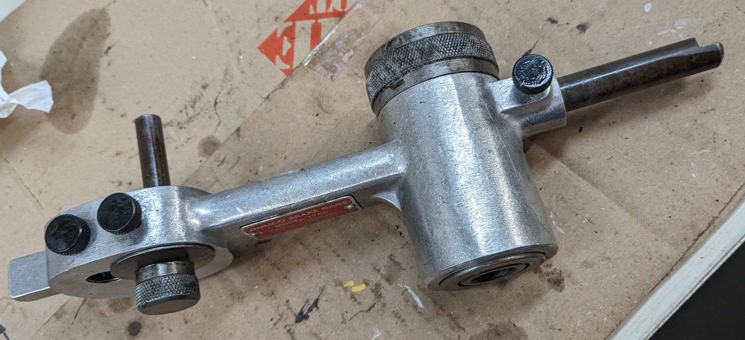
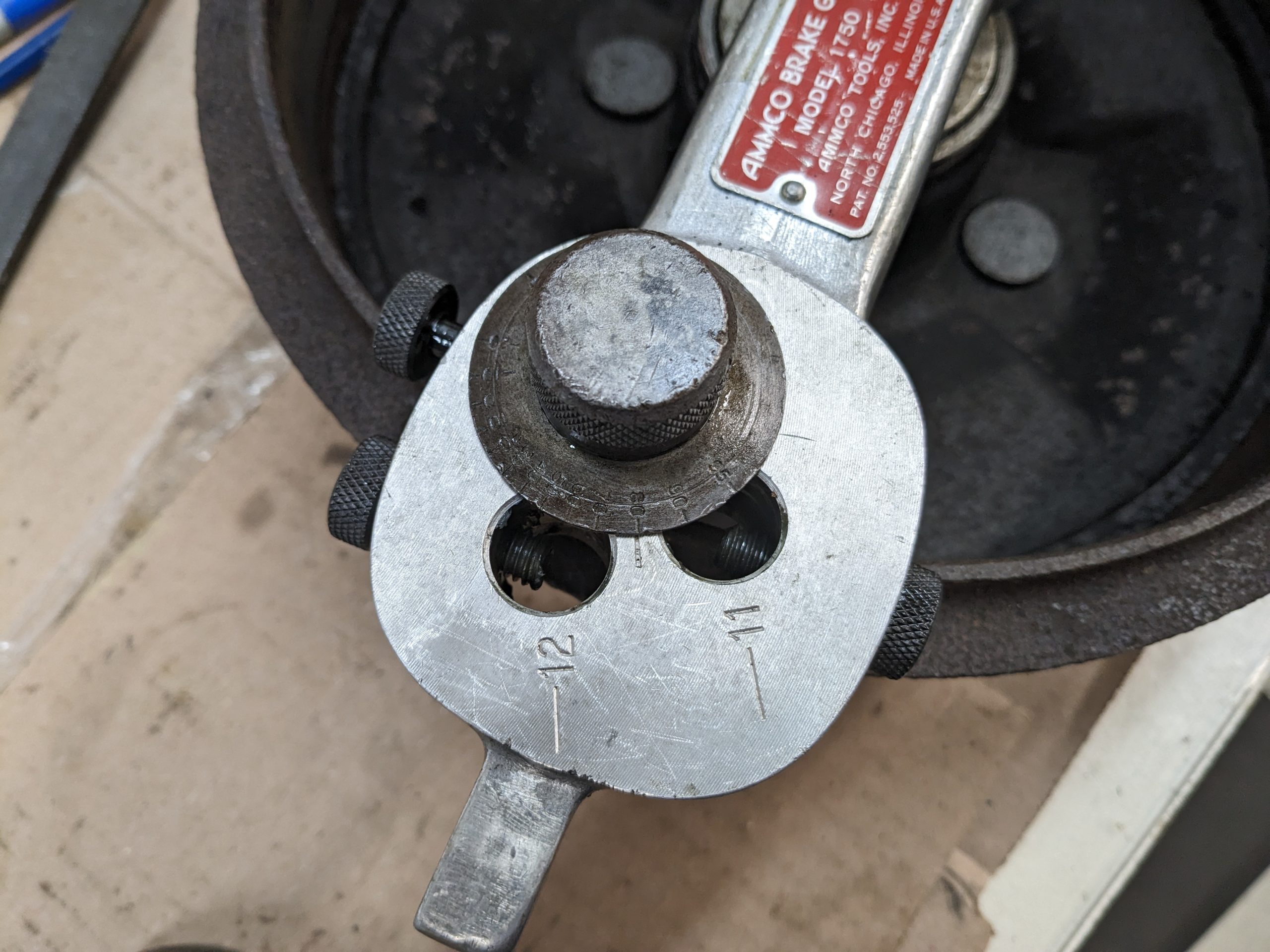
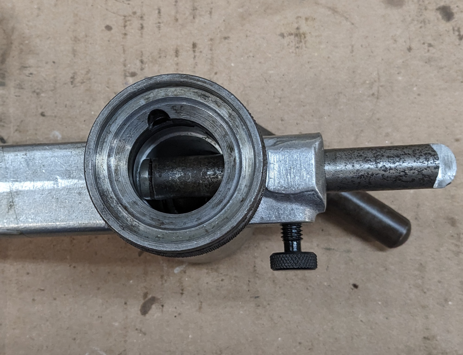
Here are all the parts to clean up and move over. Some surface rust and the set screws are beat up, but the nicer body has all the set screws.After much cleaning and rust removal here is the fully assembled tool. The steel parts had some sort of bluing or phosphate coating that did not survive well. I ended up using gun cold-blue on the steel parts later. The tool is simple to use. That notched rod sticking out the right site hooks over the brake drum, then you turn the eccentric knob to measure the drum. Then you put the tool over the axle and adjust the brakes until the gap between the pin and the shoes is even and the shoes are close to the pin. That means the brake shoes are centered and close to the correct distance from the drum. I pulled out a brake drum from my parts stash to try it out. Right about this point I realized that the tool has holes for 10″, 11″, and 12″ brakes, but my car uses 9″ brake drums. This was disheartening. I thought at first I had totally wasted both time and money. But then I started looking at it. The metal rod to measure the drums is just a hunk of round stock. And for adjusting the brakes all I have to do is get the pin 1/2″ closer to the shoes. I can’t really move the pin, but maybe I can make it bigger…
At this point let me stress that I am not a machinist and my tools consist of a nice drill press, a bench grinder, a vice, and a crappy mini-lathe that used to belong to my father and that I have never used. But fortune favors the bold. Time to MacGyver this thing.
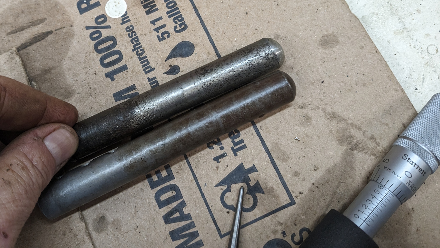
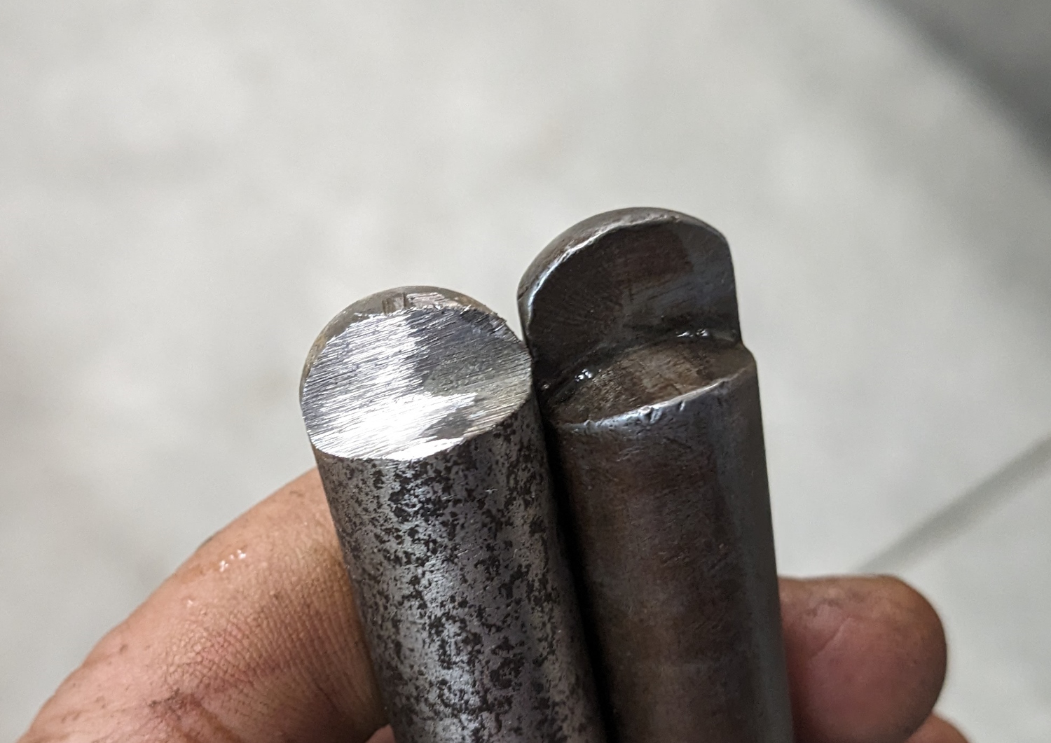
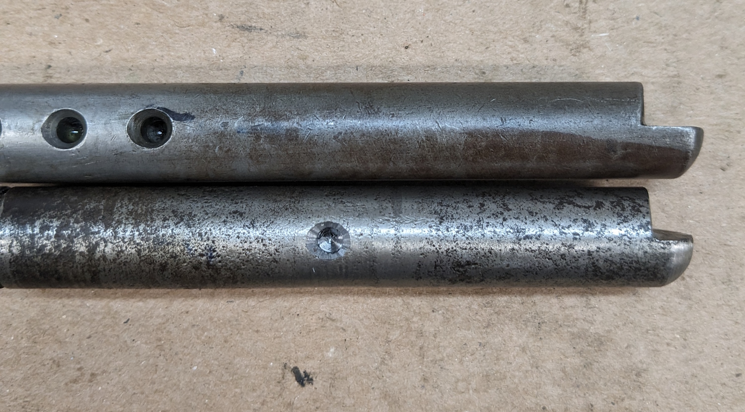
The notched rod for measuring drums is just a round bar with three holes in it for the set-screw. One hole each for 10″, 11″, and 12″. Since the dial pin at the other end moves out 1/2″ for each size drum, the holes in this rod are also 1/2″ apart. The pin can’t move in any more, but there is no reason the tool has to be centered in the drum to measure it. So a hole 1″ in from the 10″ hole would make the rod measure 9″ just fine. But the rod is too long and bottoms out. So I need a shorter rod. I found this pitted chunk of round stock in my scrap bin. I think it was part of an axle shaft for a lawn trailer or something. It is not pretty, but it is the correct diameter. Step one, round the end off like the original rod. I used the bench grinder to rough this in, then chucked the shaft into the lathe and used a file to smooth out the curve. Not bad for a first step. Now it gets ugly. You can see the original rod on the right has a notch cut out with a rounded face. This would be fairly simple with milling machine but I don’t have that. So I used the bench grinder to notch the rod. Keeping the notch square and straight was a challenge. This is how it looked before I started curving the face of the notch. I tried to to that on the grinder, but did not have the control I needed to to it neatly so I ended up using a file in the vice.The next trick was to get the hole for the set screw in there. According to my measurements, the 10″ hole on the original rod is .159″ in diameter. I stuck a drill that size in the hole and measured 1.545″ from the face of the notch. to the opposite side of the drill. I wanted the new hole 1″ closer so 1.545 – 1 – .5 * .159 puts the center of the new hole .4655″ from the face of the notch. It is also important the the axis of the hole be parallel to the notch. After measuring twice I carefully drilled the .159 hole to the same depth as the other holes. I then tried to bevel the edge of the hole but got some chatter. It is OK, but not great. When I went to test-fit the new rod it was a bit tight so I put it back in the lathe and polished it with emery cloth. After that it fit perfectly. Her it is installed and the set screw in. I just had to grind the opposite end a bit to clear the back of the hole Measuring a drum with the new shaft. The pin on the left is mounted off center and the dial has numbers for measuring the amount above and below nominal size. I set up two chucks of steel as close to 9″ apart as I could measure and put the tool on. I ended up making the new rod about .025 too short, which I can certainly live with.
Now for the adjusting side of things. Since the axle goes though the bearing in the center of the tool that can’t move. On the outboard end are three holes for the eccentric pin, all 1/2″ apart but no real room for a fourth 9″ hole. But if I could make the pin 1″ larger in diameter that would be the same thing. I measured the pin at 0.46585″. That is a very odd size. I would have expected a standard drill size but the closest is 15/32″ at 0.4688. The tool has been beat up, so maybe the pin is smaller than it used to be. Or they just picked a strange size. Whatever. If I can make a sleeve 1″ larger (1.46585″) then the distance from the center of the axle to the pin will be 4.5″ and everything will work out. So I need a tube of metal 1.75″ long, 1.46585″ O.D., and .46585 I.D. Looks like I get to use the lathe.
The lathe is a Taiwanese 7″ by 12″ mini-lathe from Harbor Freight circa 1991. I watched a bunch of YouTube videos and read web pages on how to use it. Then I started making chips using a brass rod I had laying around. My first few attempts at facing and turning to a diameter were a hot mess but I got better once I figured out how to lock down the cross-slide and carriage correctly.
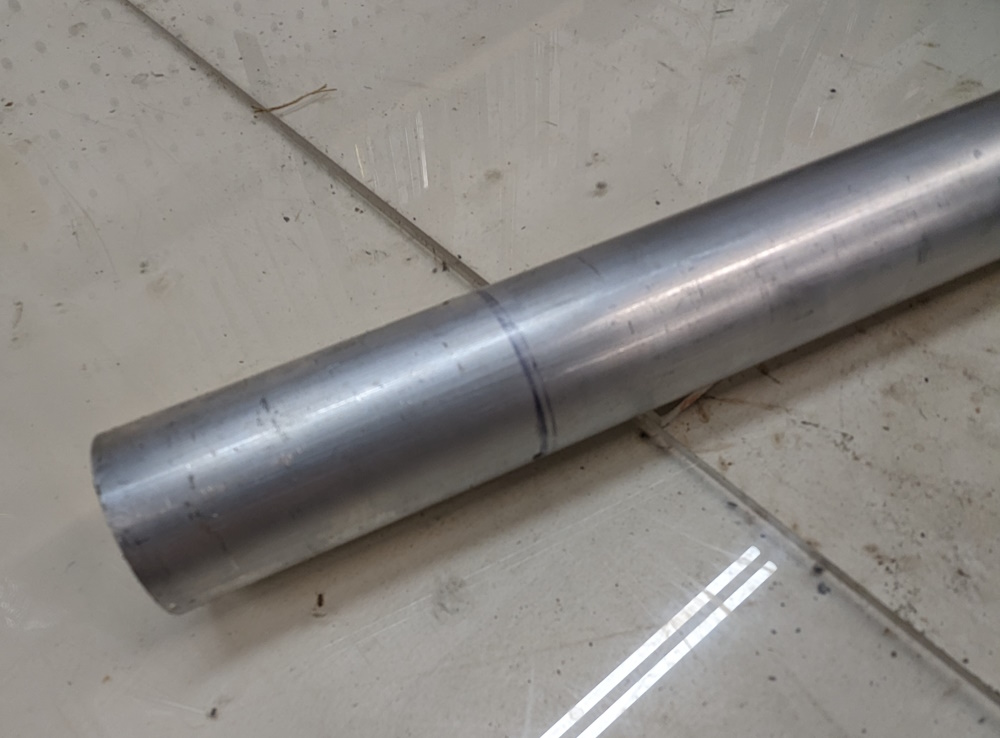
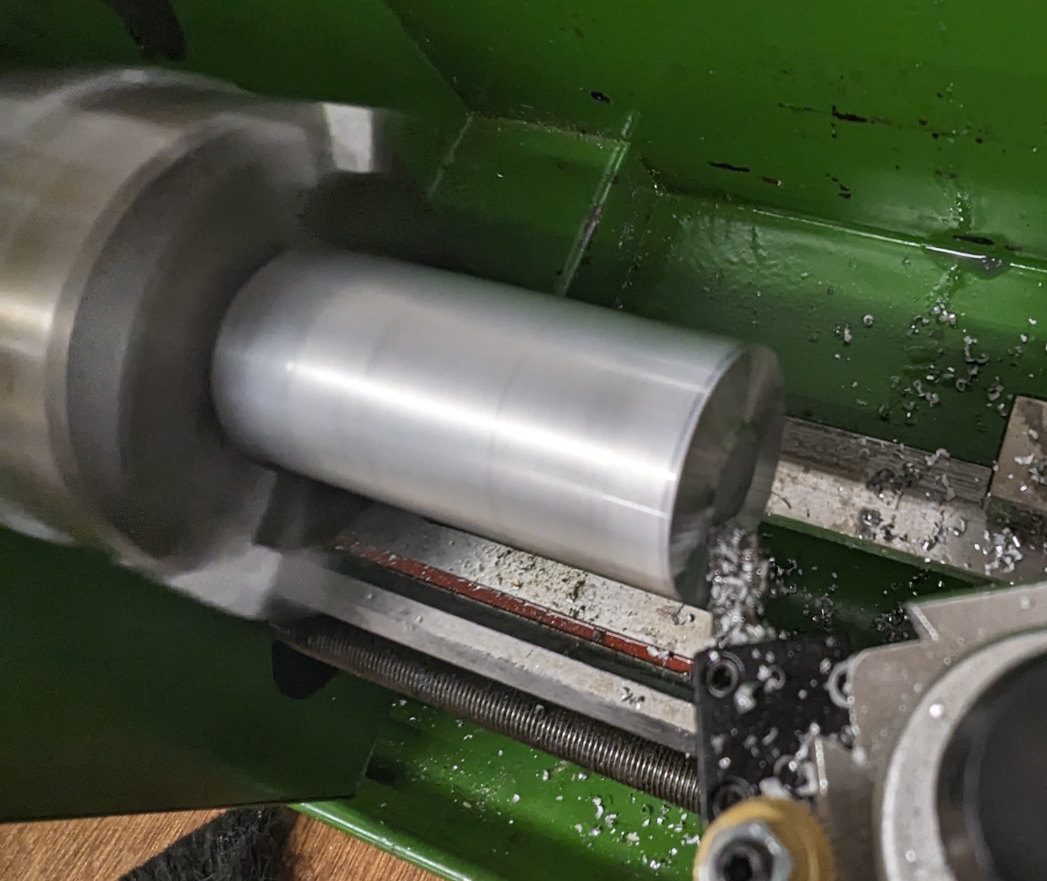
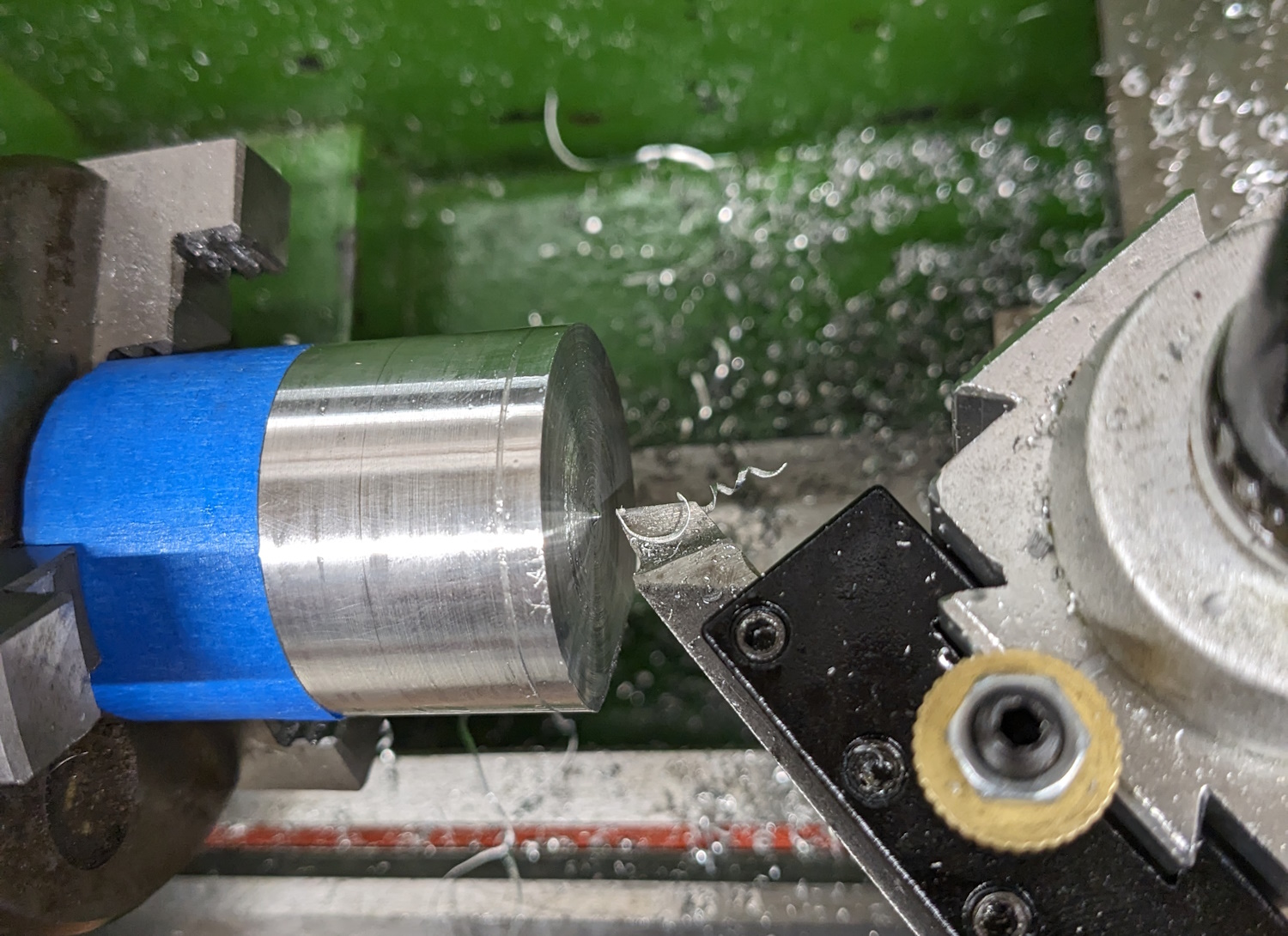
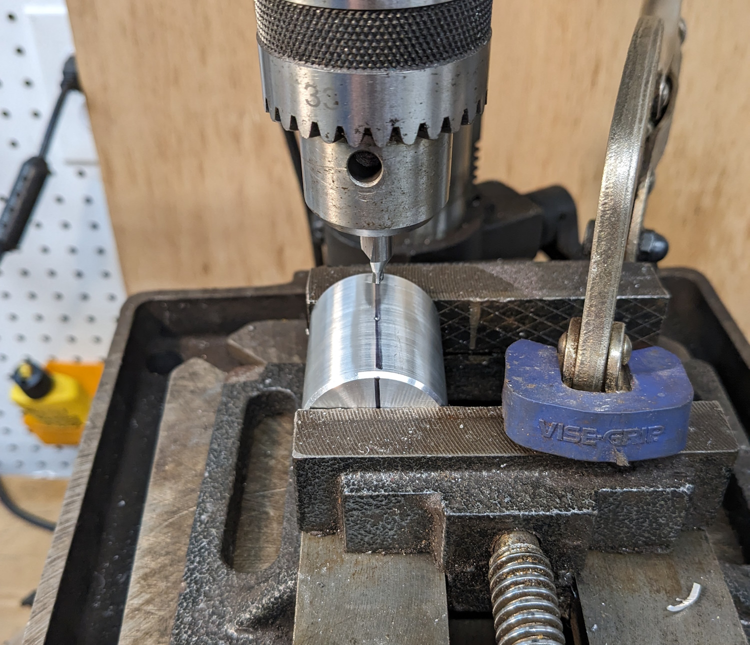
I would have loved to make the sleeve out of brass. Brass is easy to work with and looks wonderful. But it is expensive. Instead I bought this 1-foot chunk of 1.5″ 6051 aluminum. Cheapest source I found was Amazon, so I bought it there. Since this cost about $20 I also bought some much cheaper 1″ stock to practice on. I need a part 1.75″ long so I marked off three inches to make my blank. That gives me 4 chances to get this right.Before my 1.5″ stock would fit into the chuck I needed to buy some outside jaws. Then I had to fool around a bit to get minimal runout on the part. Every time I put the part into the chuck I checked runout with the dial indicator. I am no machinist, but I am figuring out that this little lathe is fairly terrible. The spindle has about .006 of side-to-side wiggle to it. New bearings would probably help but for right now I am going to make it work. First step is to face off the part. That will establish my first machined reference. With a little fooling around I got a nice, flat, smooth cut. This lathe does not have a carriage lock so I have to use the nut on the lead screw. It takes some fooling around before every cut to get everything locked down so I don’t get a cone instead of a flat face. If I keep doing this I need to build a carriage lock for this thing.The part is long enough (and this lathe is none too rigid so I want to use the tailstock to support the end. So I center-drilled it.Now I can turn the part down to the proper diameter. This is the first dimensionally critical operation. I am aiming for 1.4659″ which is exactly 1″ larger than the pin on the brake tool. To get a nice finish I am using a rounded cutting tool. On this first pass I cut a little deep and a little slow, so you can see the finish is not great. I got it dialed in. My final dimension ended up at 1.466″. Close enough!At this point what I wanted to do is drill the center hole out without removing the part from the chuck. That would ensure the hole is exactly parallel to the outside and perpendicular to the face. But the lathe is just too damn short. I can’t get Jacob’s chuck, drill bit, and tailstock to fit without make the part shorter first. So I pulled it out and chopped off the extra. I put it back into the chuck with some tape to try and protected the machined finish. This turned out to not be my brightest idea. I also measured and marked the final length. You can see that line in the part. I have more than 1/8″ of metal to remove. After dialing the part in I started taking facing cuts. This was going well until I tried to take too heavy of a cut and the part twisted out of the chuck. I did not get hurt but the part got dinged. Frustrating.
Now I had a problem. The inner hole needs to be a hair larger than .46585″ I don’t have a reamer that size and my one boring bar can only cut down about an inch. Twist drills do not make very precise holes but that seemed like my only option. If the drill failed, plan B was to buy a 4″ or so boring bar and use that.
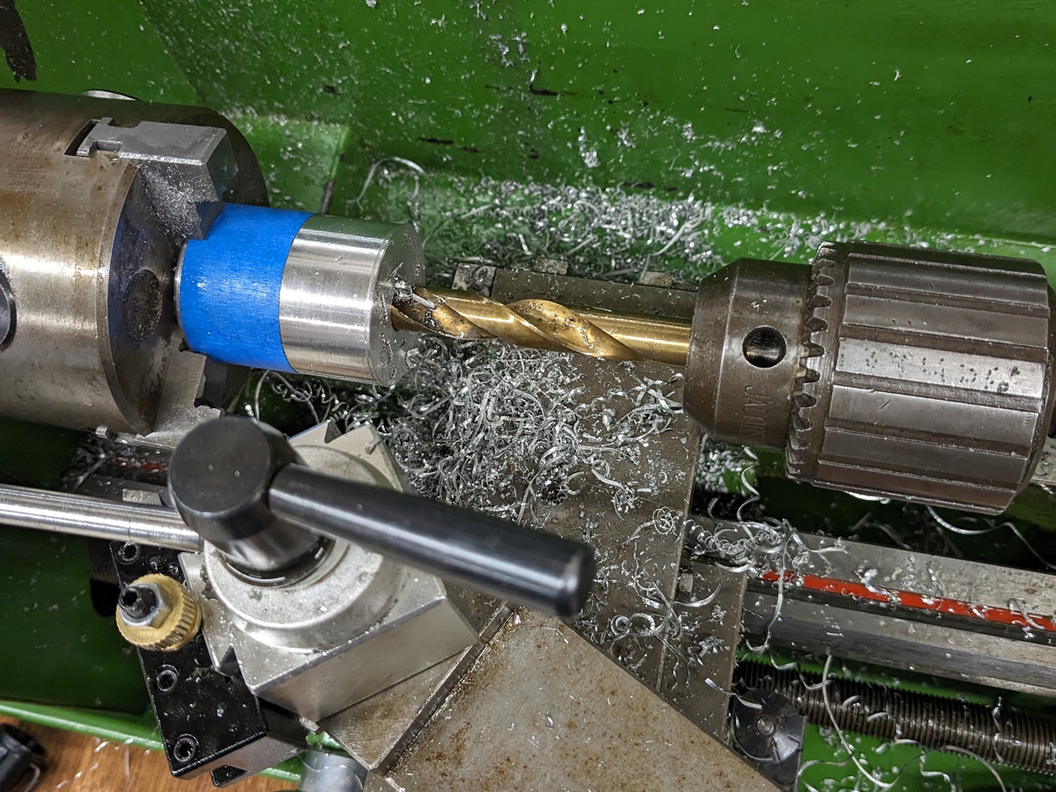
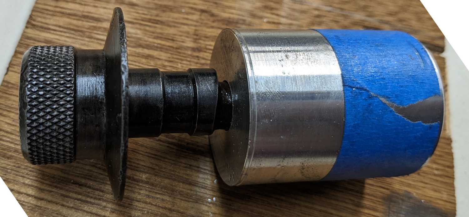
The secret to getting a decent hole from a twist drill is to ramp the hole size up slowly. I started with a center drill, then drilled through with a 1/8 bit and worked my way up from there. Once again the stupid-short 12″ ways on the lathe caused me pain. My Jacobs chuck is a long 1/2″ chuck with a full-size #2 Morse taper on it. When that is seated in the tailstock I only have about 1″ of travel on the tailstock. My part is a little less that 2″ so you can’t go all the way through in one cut. So I had to take a cut, move the tailstock forward, and repeat. As the drill bits get fatter they get longer and the problem gets worse. If this part was made of steel I would never have made it work. The final drill size is 15/32″ which is .4688″ That drill is so long that the setup was super sketchy. You can see the tailstock is barely on the ways. But I got away with it. It is a loose sliding fit but good enough. I chucked the part up again then faced the part down to final length. I also put bevels on the edges. Now we need a hole drilled and tapped for a set screw. I marked a center line, clamped it into the drill press, and made the hole.Here is the final part. It looks really nice except for the big gouge caused when it came out of the lathe chuck. Still, considering this is the second thing I have made in the lathe (I did a test part with 1″ stock) I am pretty pleased. Here is how it works on the tool. Once I measure the drum diameter and get the pin set I just slip the sleeve on and adjust the shoes to be just shy of the sleeve. Perfect. I really want to test it out but I just don’t have time right now. More to come.


Pingback: Adjusting the brakes | 1941 Studebaker Champion
Pingback: New(er) front brake shoes | 1941 Studebaker Champion