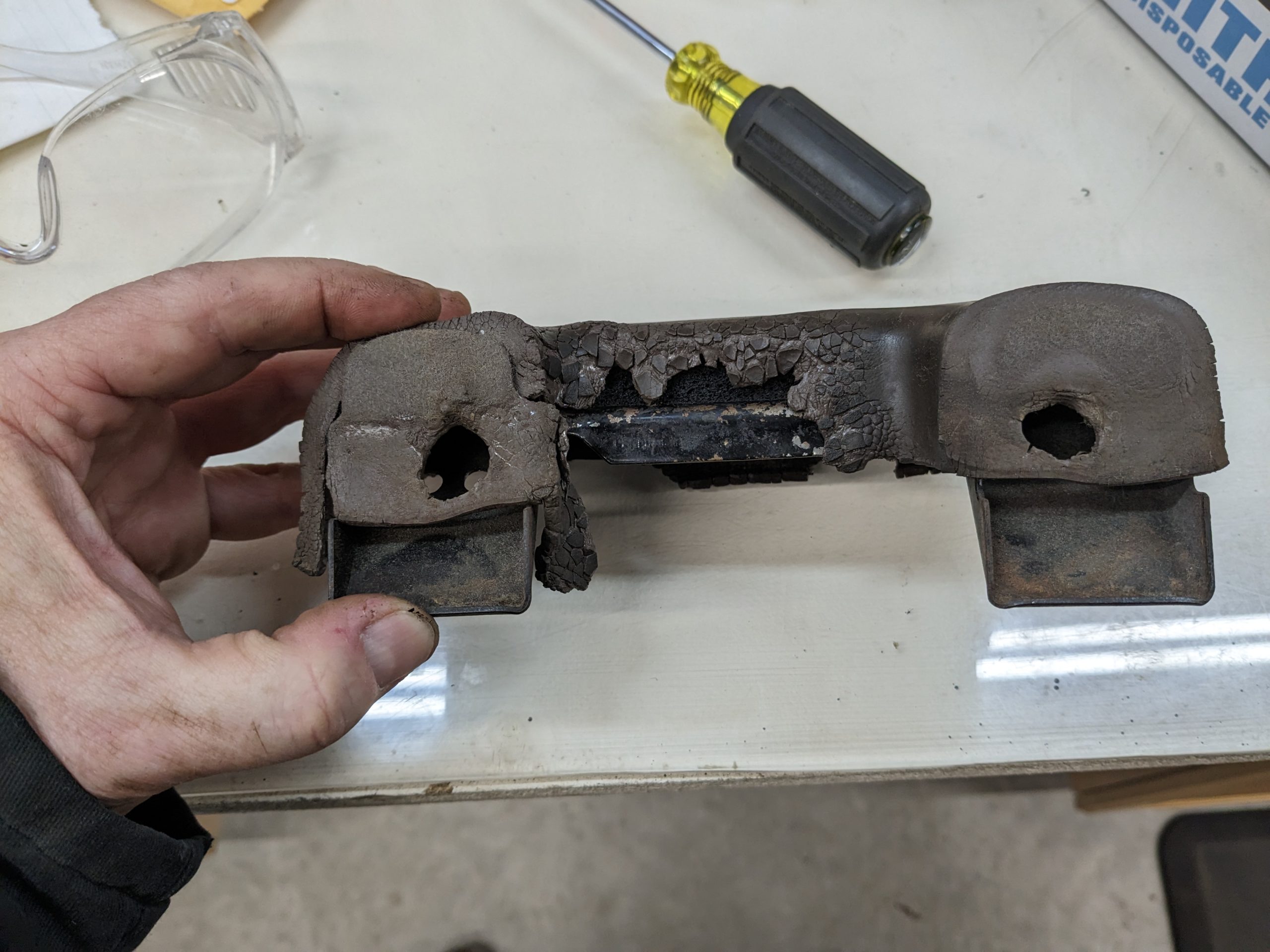
I was taking my neighbor for a ride and the door did not want to latch. The problem was not hard to find.
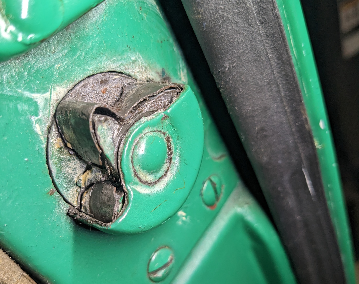
The latch was badly worn and had been repaired at some point by a carefully shaped strip of metal that was fitted around the worn star wheel and welded together. I could have just tacked it together again but this only ever worked OK, sometimes the door was prone to popping loose. I wanted a better fix.
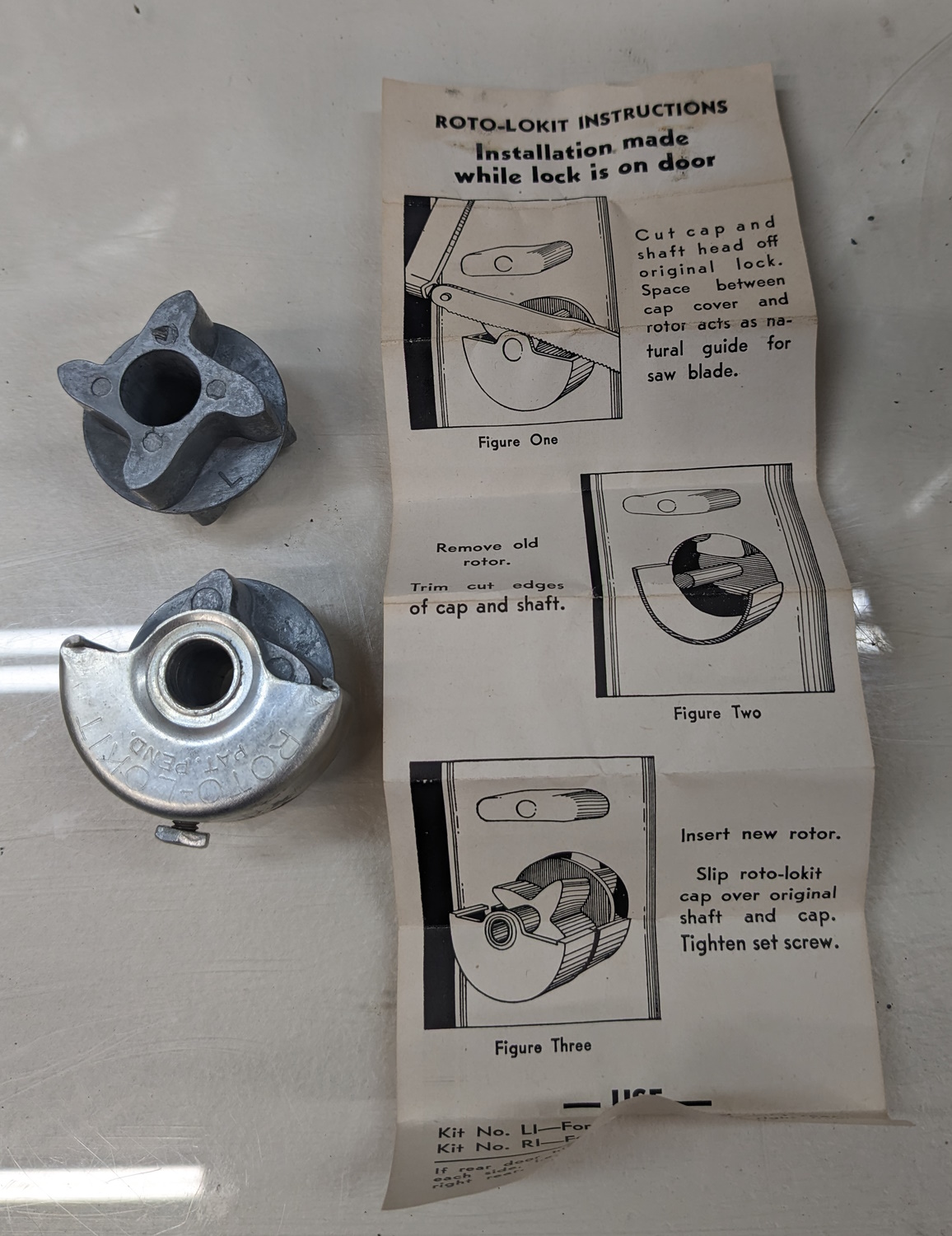
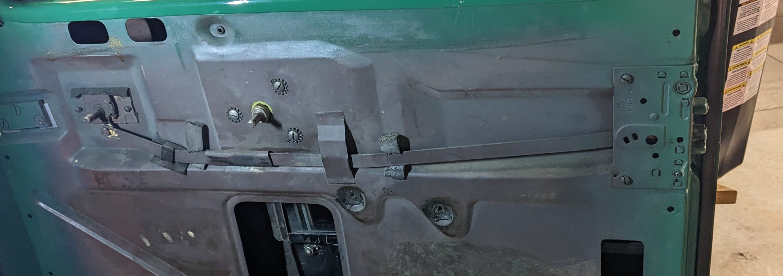
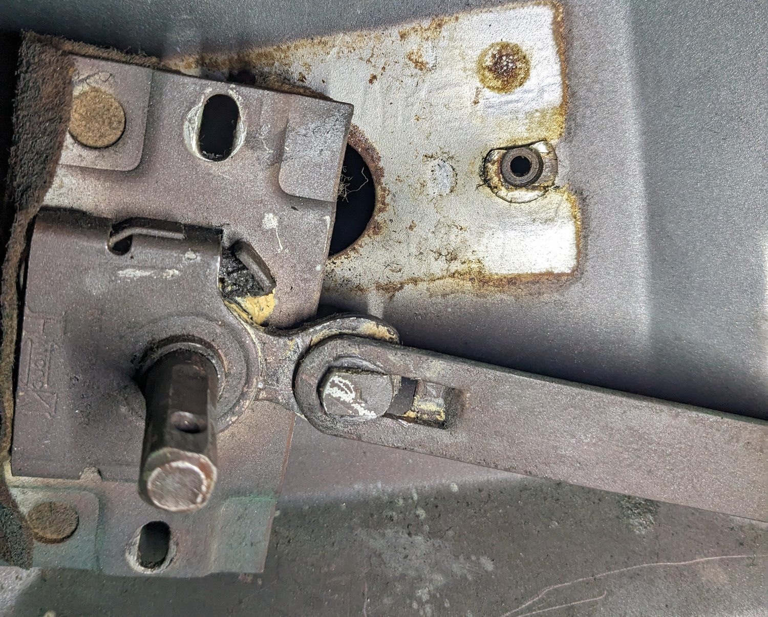
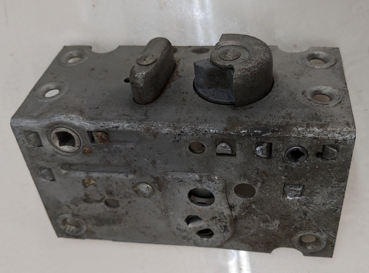
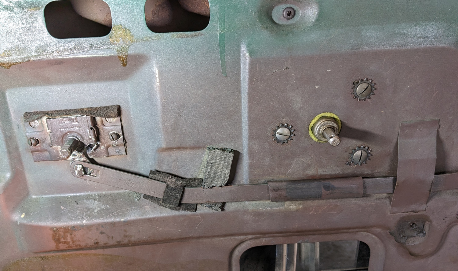
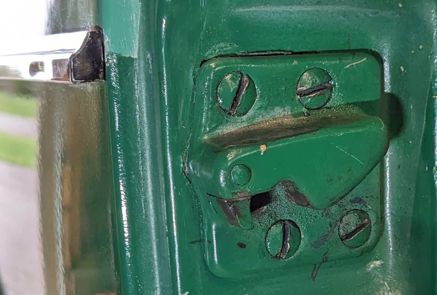
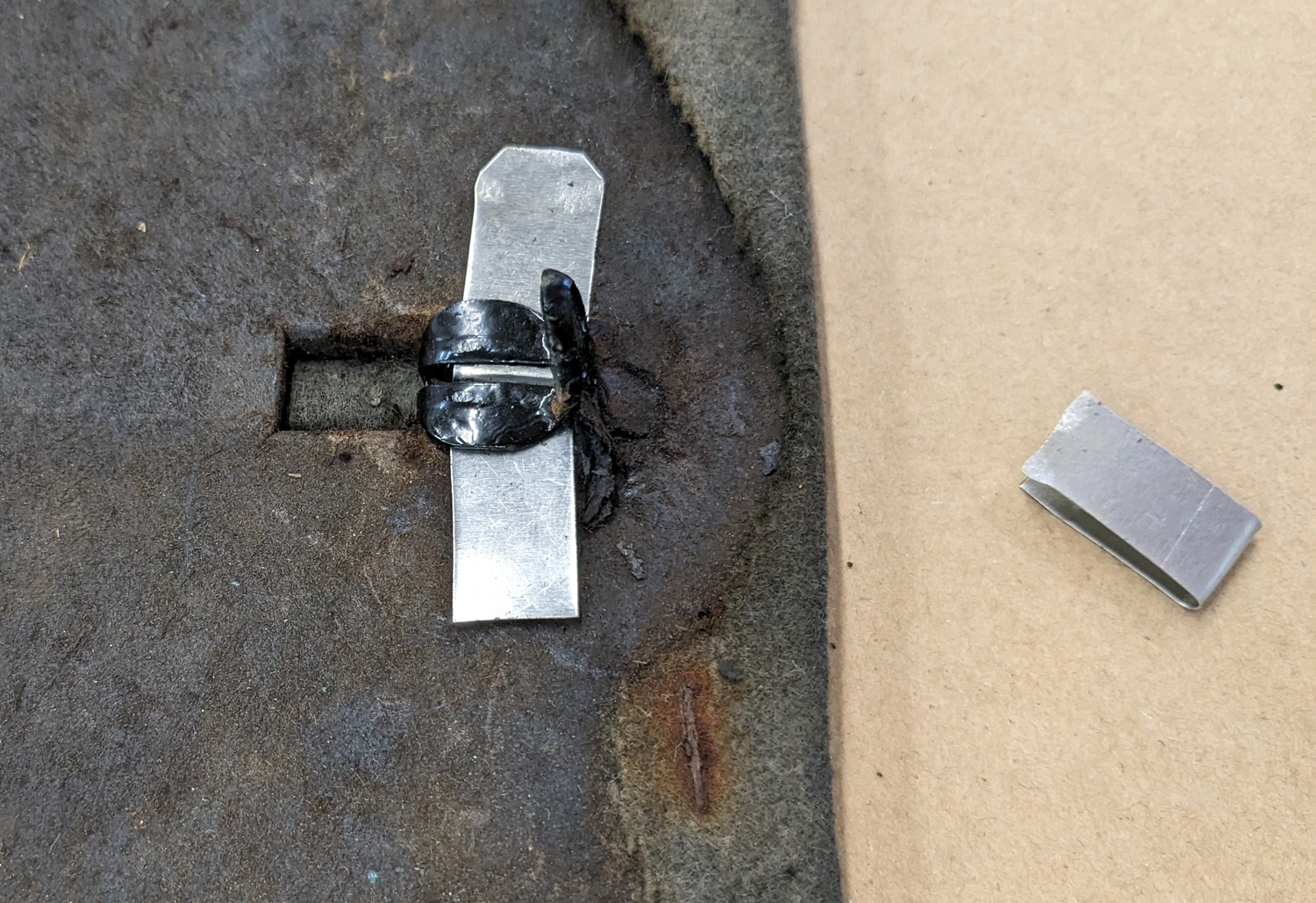
I picked this Roto-Lockit repair kit on e-Bay a few years ago. It would probably work, but seems a little hokey. I would also have to chop up the latch with a hacksaw to fit it. Once I do that , there is no going back. As luck would have it, I got the latest Studebaker International catalog and they offered a latch rebuild service. It was something like $125 but the latch would be like new. But I had to remove the latch and send it to them first. With the door panel removed, here is the latch mechanism. The “remote control” that the door handle attaches to is at the left. It moves that long bar back and forth to the latch. The outside door handle shaft is the square shaft you can see at the top of the latch plate. The key lock turns the smaller square shaft at the bottom of the latch.
The important detail here is that the bar goes under that spot-welded “bridge” on the inner door skin. So the bar will have to slide out to the right.
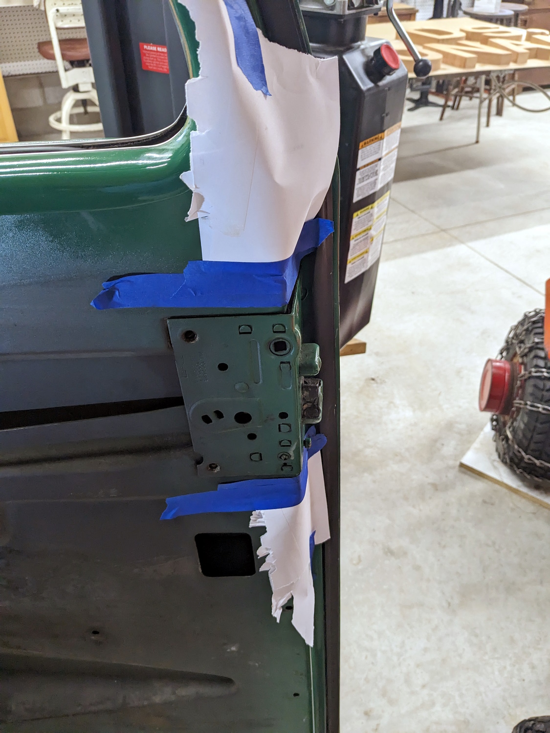
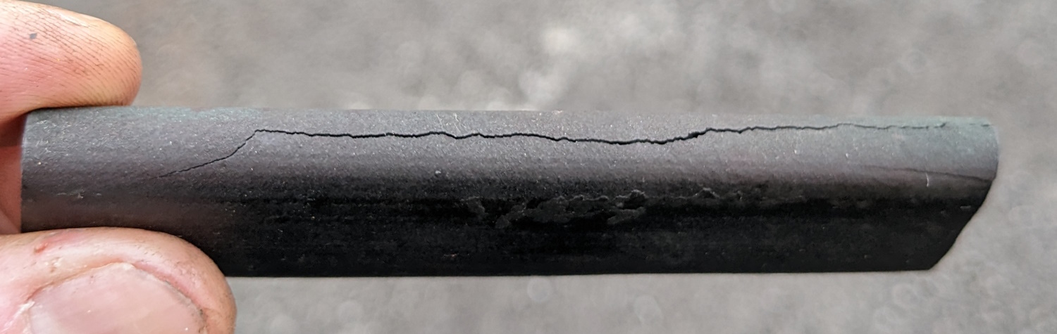
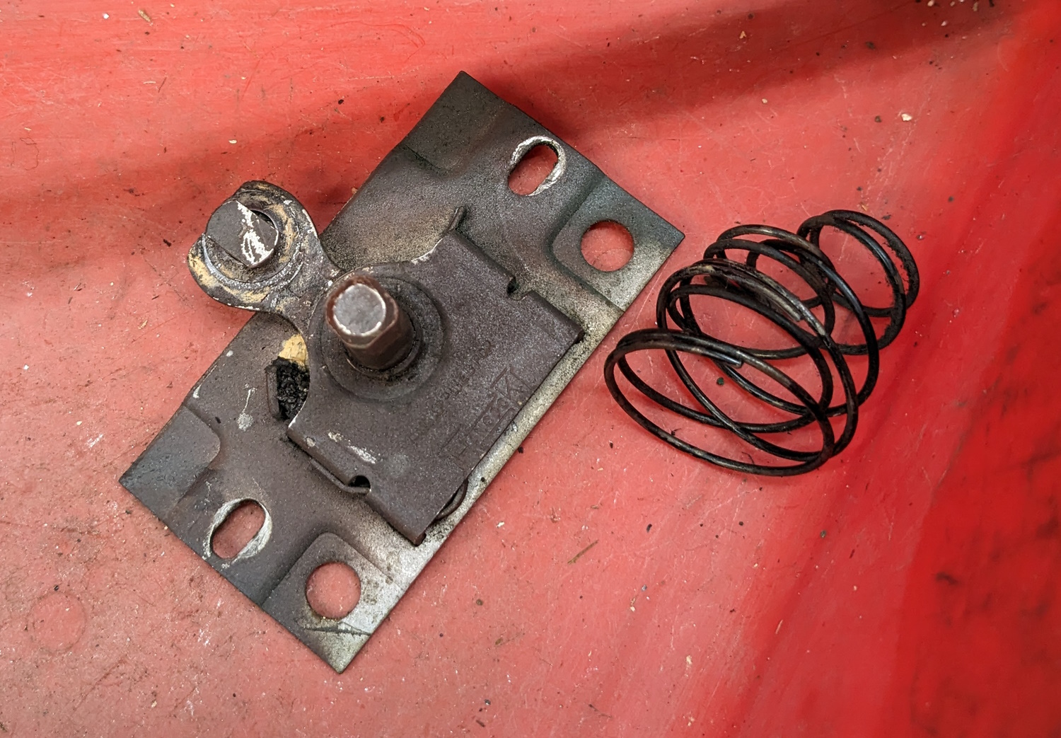
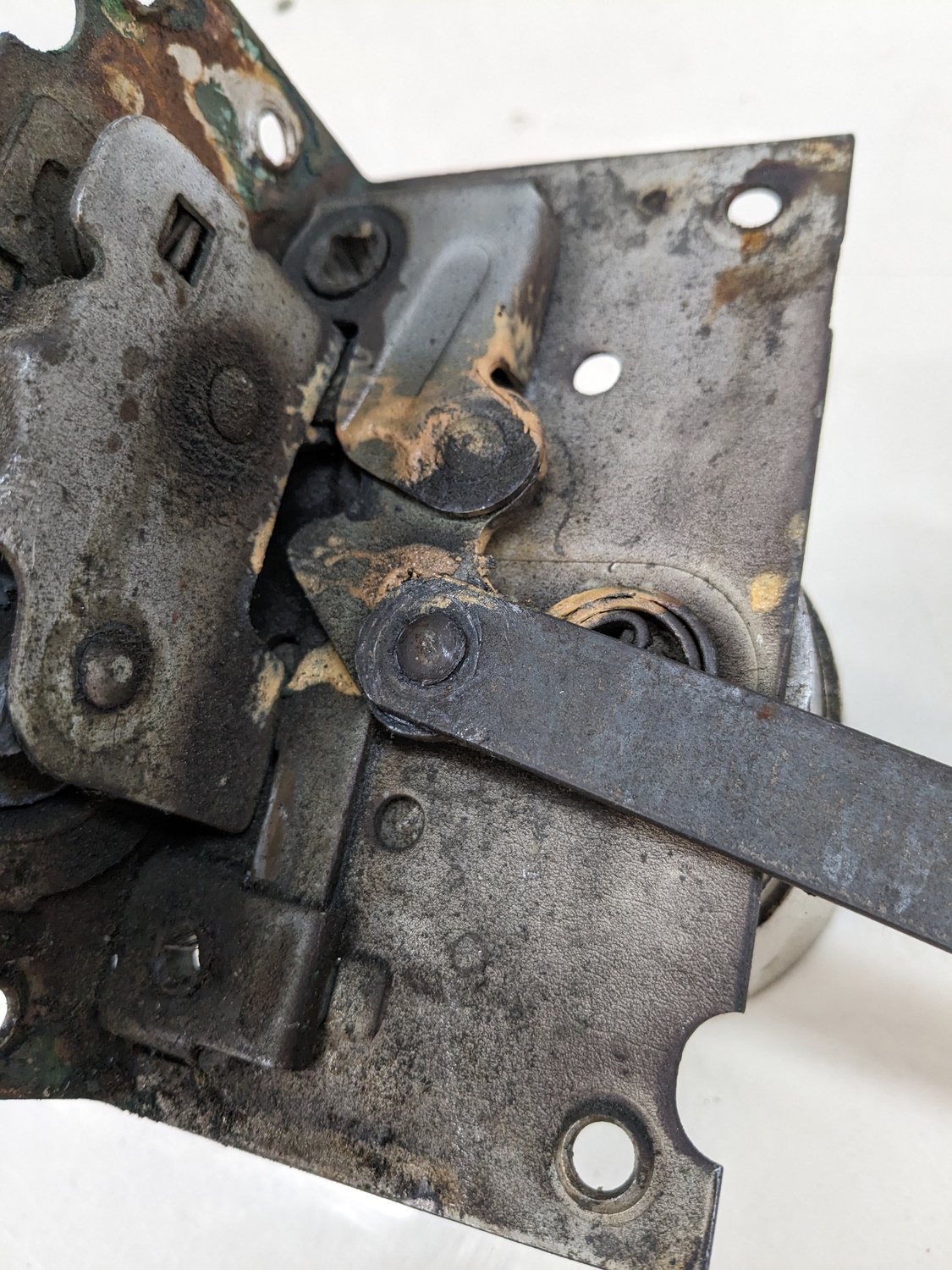
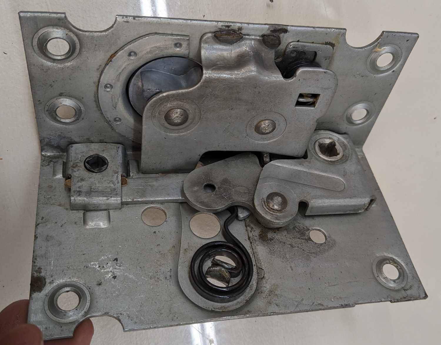
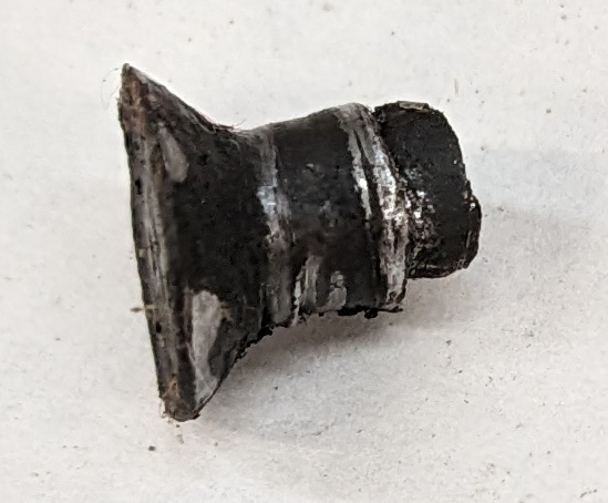
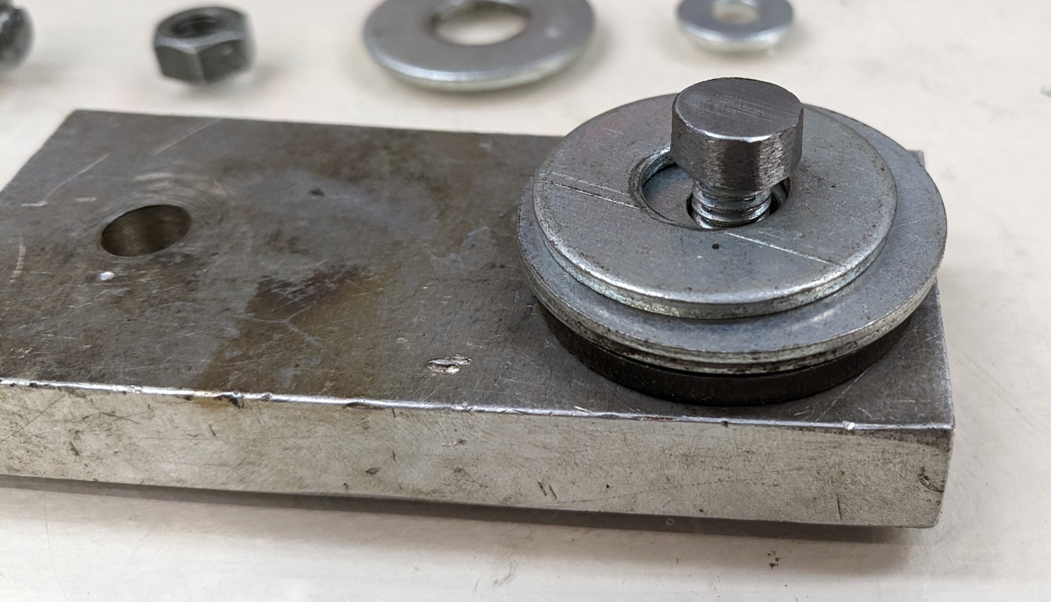
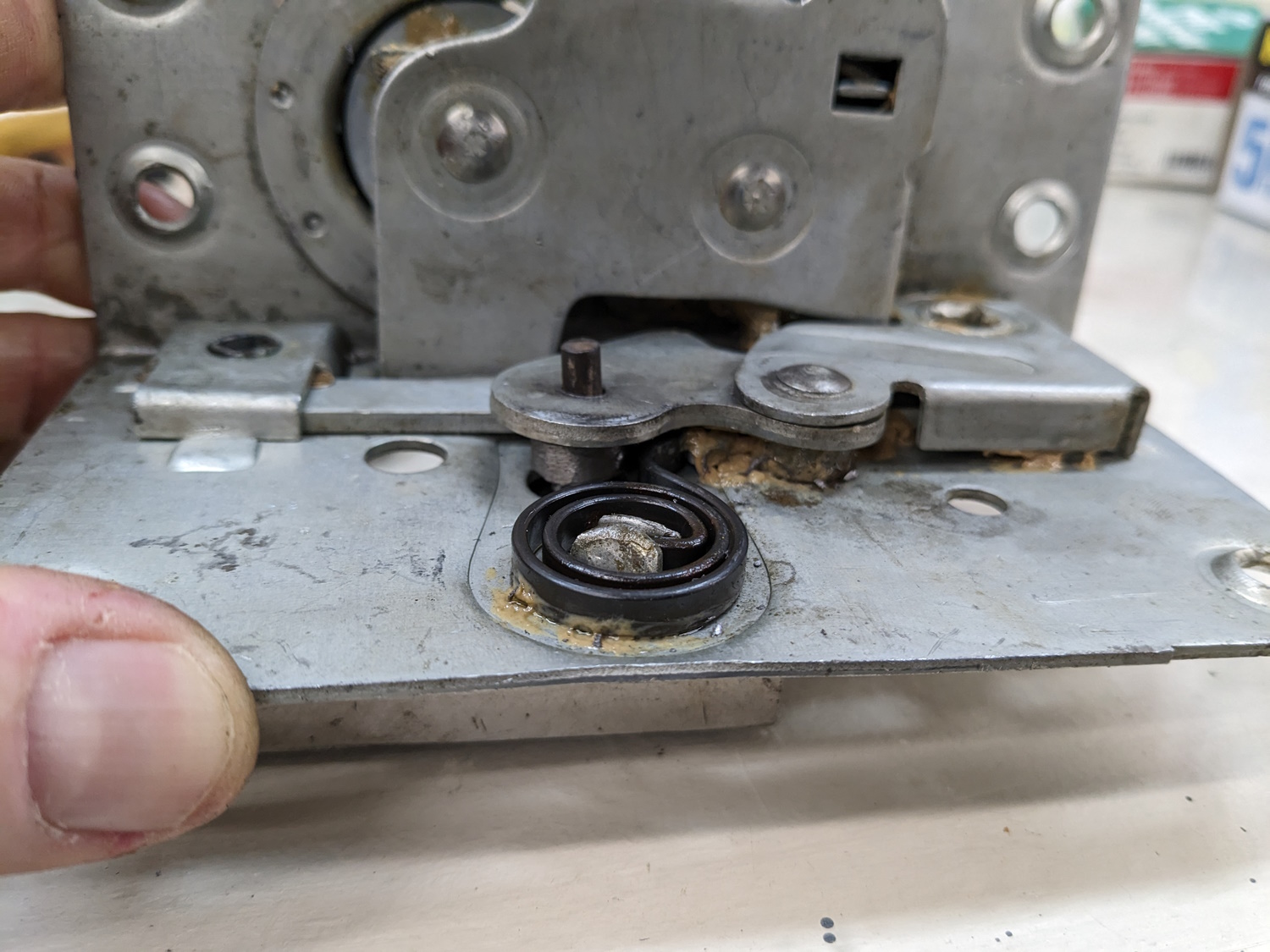
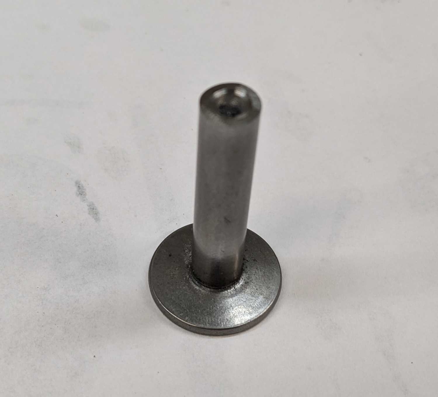
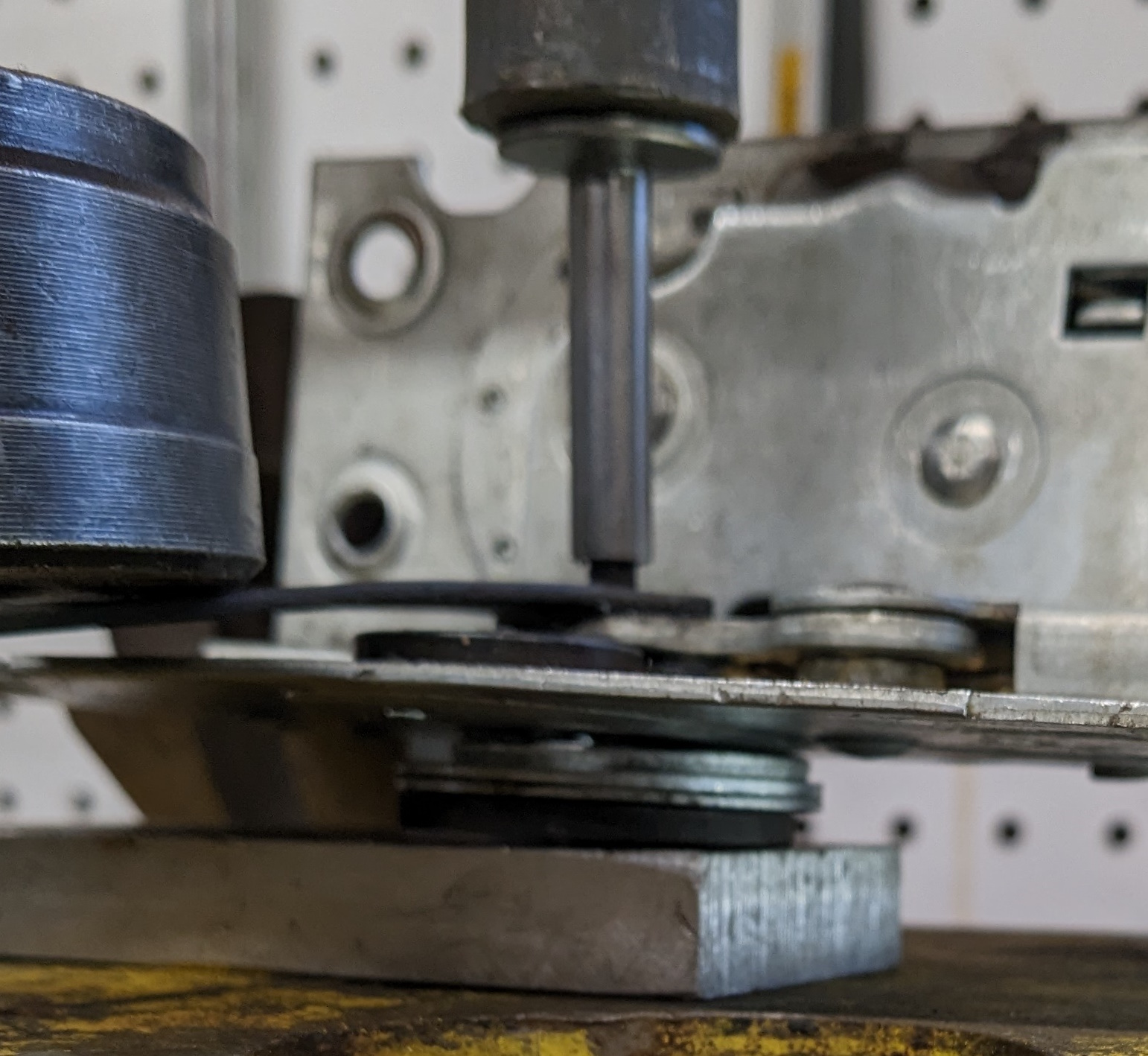
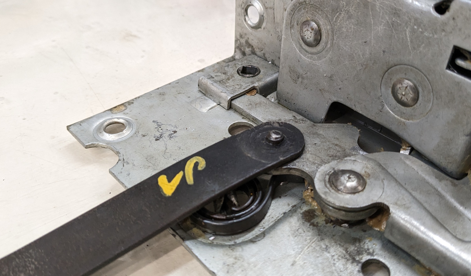
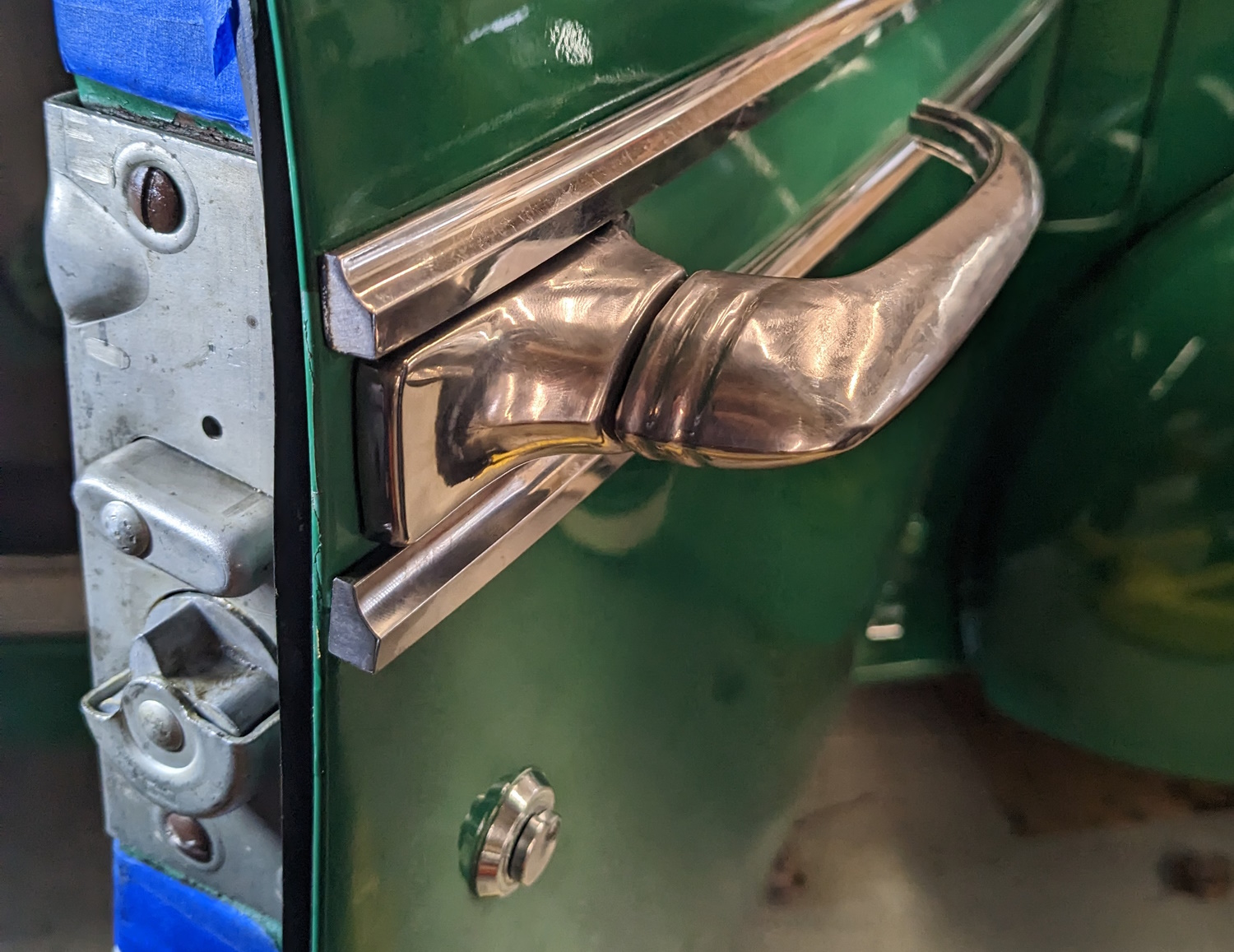
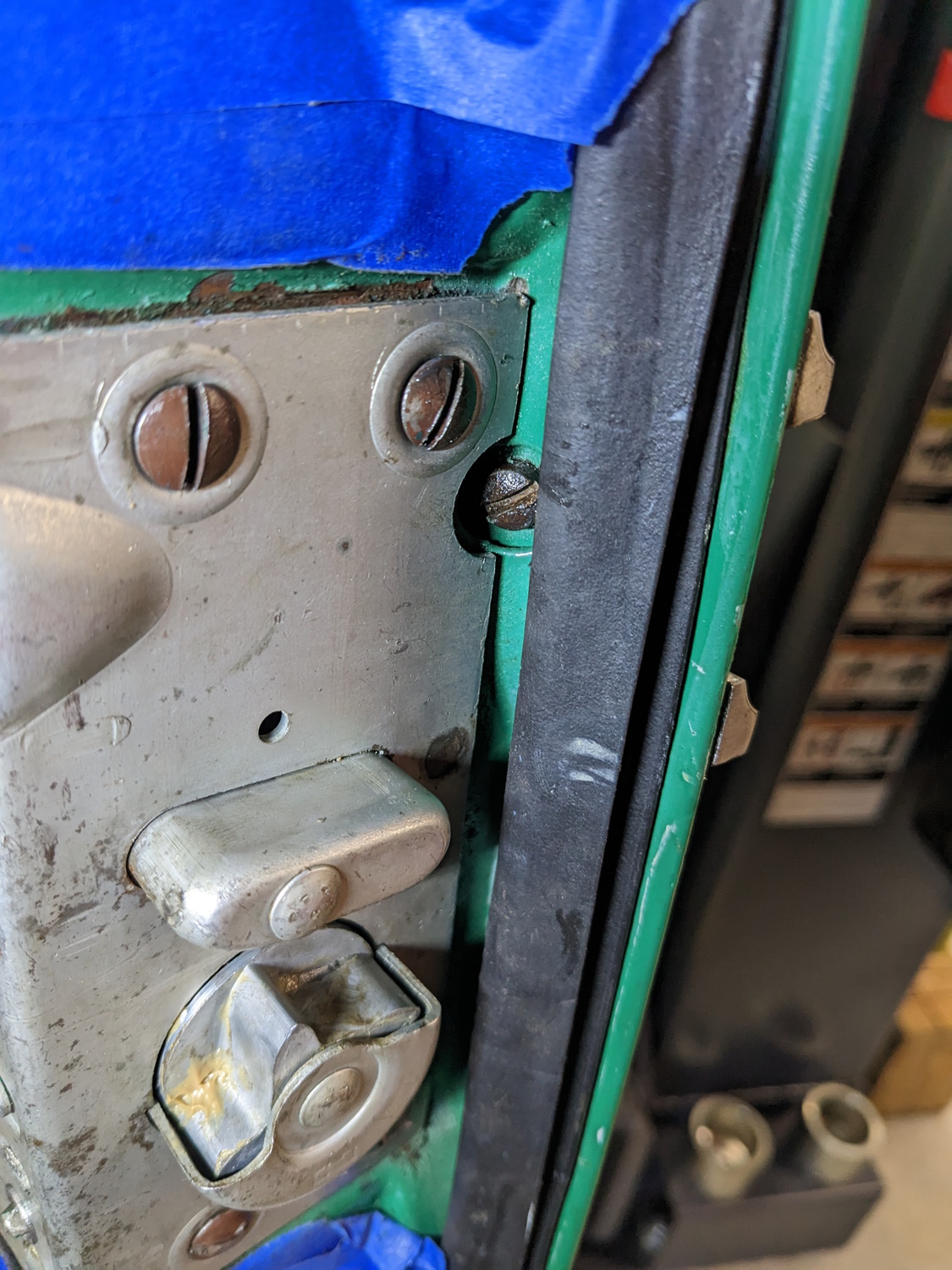
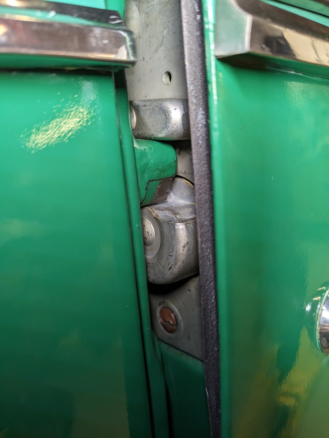
First things first. I anticipate the latch flopping about as I try to get that bar to the remote control off. To avoid any paintastrophies I taped some protection on there.This looked simple enough. I removed the screws from the remote. That allows it to rotate and it should just fall out of the bar. But it didn’t. It appeared that years of wear had distorted the end of the bar and/or the square “top” on the remote control lever. I could not get it to pop apart. I was afraid to get too violent because the bar is fairly thin mild steel and I did not want to bend it up. But after about an hour of wiggling and twisting I finally wedged a block of metal under the bar to support it and tapped on the remote lever with a brass rod until it came apart. Before I could remove the latch and bar, I had to take off this rubber anti-rattle tube. It just keeps the bar from vibrating against the door. The rubber is very hard and split pulling it off the end of the bar. Luckily it split on the bottom, so I am just going to leave it for now. If it gives any problems I have a couple ideas how to fix this. I can also remove and clean up the remote control. Those two springs go behind the door handle and window crank to keep the trim ring and door panel pushed up tight against the handles. Once the bar is loose, the outside door handle has to be removed. Then there are 6 screws that hold the latch to the door. And sure enough, the bar is riveted on this end. I ground the head off the rivet, removed the bar, and sent the latch to Studebaker International for rebuild.In about 10 days I got this back. It is not the same latch, and is either NOS or was rebuilt some time ago because the grease in it was petrified and it was pretty dirty. The good news is they also had a replacement rivet. Part number G104150 if you need one. Spoiler alert: I sure did. I cleaned up the latch and re-lubricated it. Now I have to figure out how to rivet it. The rivet goes though that 1/8″ hole in the lever in the middle of the picture. The only access to the back of that lever is though that 1/2″ hole you see right below the lever. Here is the remains of the old rivet. The rivet is a flush type and fits into a taper on the other side of that latch lever. The “shop head” of the rivet faces towards the door. I need to some up with something flat to support the back of the rivet tight against the lever and something else to form the shop head in my press. This is going to be interesting.After a lot of fumbling around and searching for potential rivet-tool parts I came up with this. The key is I have to have something flat to back up the rivet that will fit though the fairly access hole in the latch. At the same time, the latch has to be supported at the same height so the lever is not twisted or bent by the weight of the latch. I had this aluminum bar with a couple holes in it. I set a bolt in the hole then “machined” the head on my grinder and with a file until it was round enough to fit through the access hole and basically flat on top. A selection of fender washers will support the latch body so the lever rests on top of the bolt. Here is how this will work. You can see the new rivet poking up through the lever with the bolt underneath holding it up. Now I have to figure out how to form the shop head.This tappet from a small engine caught my eye. It is strong, straight, has that big flange to push on, and already has a dimple in the end that is rivet head shaped (if you squint). I used the bench grinder and a die grinding stone to make the dimple shallower and wider. Lets see if it works! I had a hard time with focus here but this is the whole rig in the press. The bolt and aluminum plate are resting on the press plate. The washers are holding up the latch. The bolt is backing the rivet. The bar is over the rivet with some scrap steel holding in place, and the tappet is between the end of the press and the top of the rivet. This worked great. Until I realized had put the bar on UPSIDE DOWN. How stupid can you get? I marked the bar, but somehow in the fooling around trying to get 6 parts lined up with 2 hands I got it flipped over. So the new rivet got drilled out and I had to wait almost a week for another one. I ordered an extra as a sacrifice to the auto-repair gods. Here is the much better second attempt. I made darn sure the bar was marked clearly this time. My shop head is higher and smaller than the factory one but it seems secure. If it does not hold I will have to re-shape that dimple on the tappet. And yes, I greased the rivet before I pressed it in there. Time to re-assemble. Here the bar and latch are in place. The latch has been slipped over the door lock shaft, and a couple of screws loosely installed to hold everything in place.All the anti-rattle bits have been replaced and the cleaned and lubricated remote control is back in . The new rivet made it a bit sticky at first but after working the door handle a few times it worked well. The remote has a die-cut piece of felt behind it for some reason. I removed that carefully when I cleaned the remote then glued it back on while I was waiting for the new rivet. Next the door handle is installed.Now I can screw the latch in. You can also see the small screw that holds the door handle on. You can see from the paint line up top that the new latch is not exactly in the same footprint as the old latch. All the holes line up, so I am assuming this latch is just a little bit different in size. No way to tell now! Speaking of painting, I did not paint the new latch. I suspect they were not painted from the factory. If I get corrosion issues I will take it off and paint it. The moment of truth! I very, very carefully closed the door. It closed, but was not latching well. Here you can see how the latch works. The upper “post” on the latch rides on the “shelf” on the B pillar. The flappy panel you see on the star wheel is the secondary latch. The wheel also catches farther in to hold the door shut. Here is the other half of the latch. This side is adjustable. After marking the current position with some pencil marks, I starting tweaking. After much dorking around, I settled into lowering the inner (right) side of the latch while keeping the outer side about the same. Now the door closes pretty well. It is not great and I may mess with it some more but frankly I got tired of fooling with it. When I removed the door panel some of the rustier clips broke and others ripped out the very, very old asphalted cardboard that makes up the door panel. I had some extra clips and used them all. I ordered more (part number 1917×3) when I ordered my replacement rivets. To fix the damaged panel I came up with these aluminum bits. They are just u-shaped strips of metal slipped onto either side of the damaged area. The spring clip then squeezes both u-shapes and holds them in place. I have no idea how well this will work. Stay tuned… I had one more problem putting this thing together. I could not get the screws for the armrest to start. I finally figured out what was happening. My car’s armrests have rubber covers (which is not correct, these are probably off a pickup truck). The rubber is deteriorating and has “melted” to the point where it is interfering with the screws. I trimmed the rubber back a bit (it is not like it is any good) and got the armrest installed. There we go, all together!Here is a close-up of the new latch. Looks good! I took the car for a test drive and put it away. I need my service bay so I can do an oil change on one of our real cars.