
The engine has not sounded right since I adjusted the valves. I already found one exhaust leak, which helped, but it still sounds wrong. Time to bite the bullet and figure out what is wrong.
Continue reading
The engine has not sounded right since I adjusted the valves. I already found one exhaust leak, which helped, but it still sounds wrong. Time to bite the bullet and figure out what is wrong.
Continue readingI was taking my neighbor for a ride and the door did not want to latch. The problem was not hard to find.
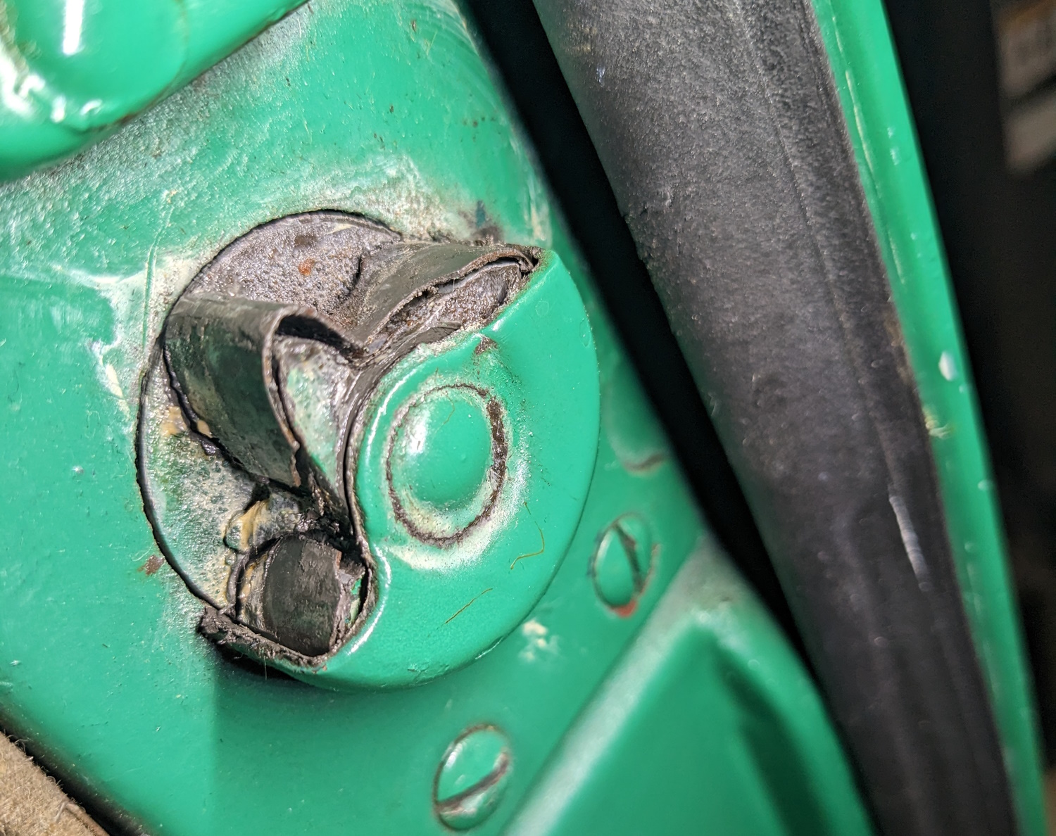
Since I did the valve adjustment the car has sounded like it has an exhaust leak. I thought it was the manifold gasket. But I was only 1/2 right. After driving the car for a while I spotted this:


My plan back when I did the wiring last year was to put a set of Unity vintage fog lights on the car for front turn signals. But I waited too long and Unity discontinued their vintage line. They make the same lights for 80+ years and I miss out by 6 months.
Continue readingBack when I did the new wiring harness I said that everything was working perfectly. It turns out that was not correct. I did not realize at the time that the new turn signal switch had a light in the handle that is supposed to blink when the signals are on. When I discovered this, I found the light was on dimly when the turn signals are off. The light blinked (dimly) when the turn signals were on. My first thought was a bad ground, so I tested that and it was fine. So today I decided to try and figure out what is going on here.
Continue readingIt has been more than 11 years since the last valve adjustment on the Studebaker and it is high time. Last time the engine was out of the car, this time I am not so lucky.
Continue readingI realize I have not been doing a lot of Studebaker work this year. Working on the new shop has sucked up a lot of time and even more $$$ but it is basically done now.
Continue readingThere has not been a lot of Studebaker work this summer because I have been working on this: We build a new 40’x26′ shop with a BendPak lift. It is going to rock but has sucked up all of my … Continue reading
I have wanted to do this for a couple of months now so when I got a sunny warm day to work with I jumped on it


This is the worst part of the job. The oil does not drain out of the filter housing so I have to pump it out. It is the better part of a quart.

